Equatorial Mount for the Seestar S50

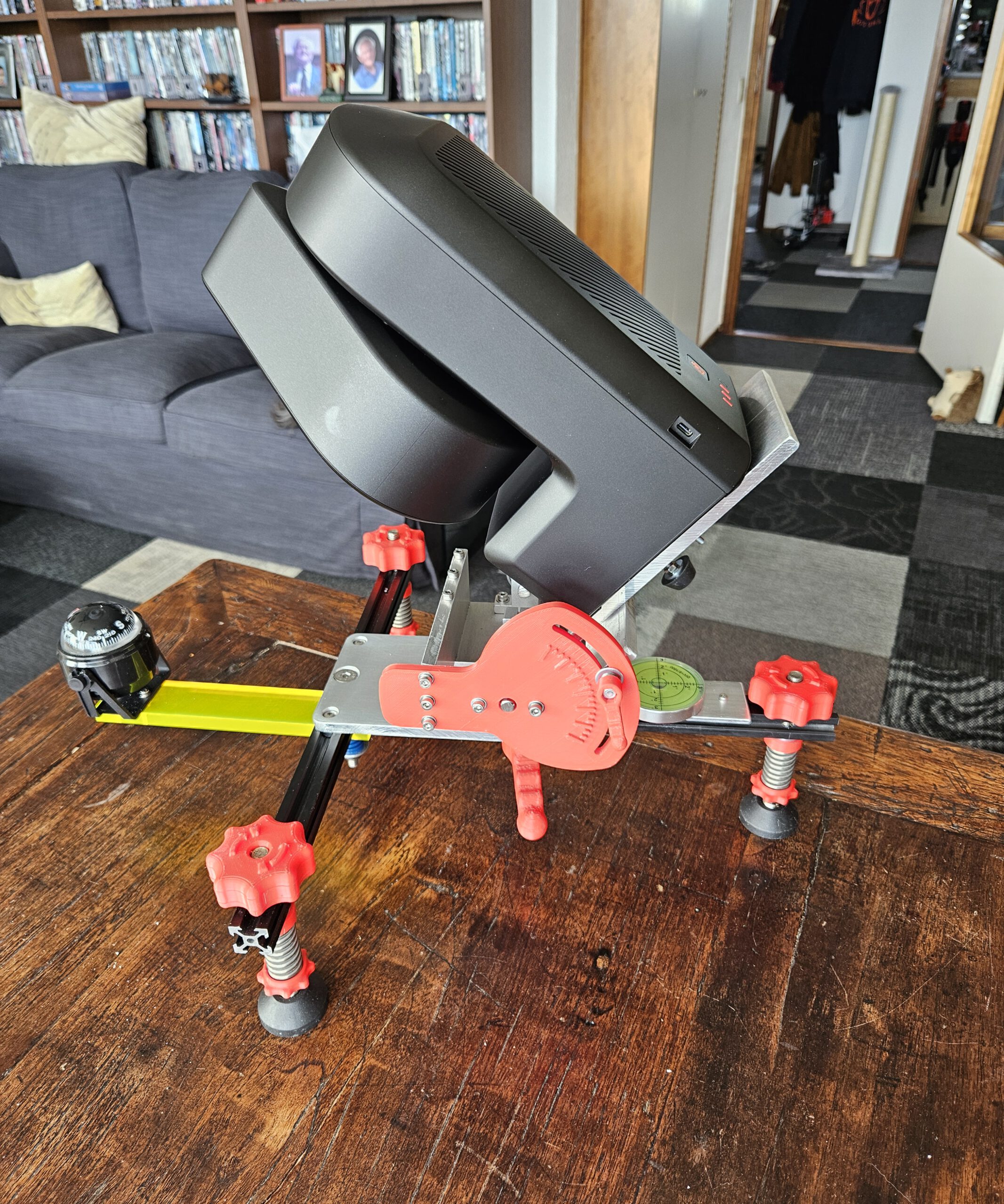
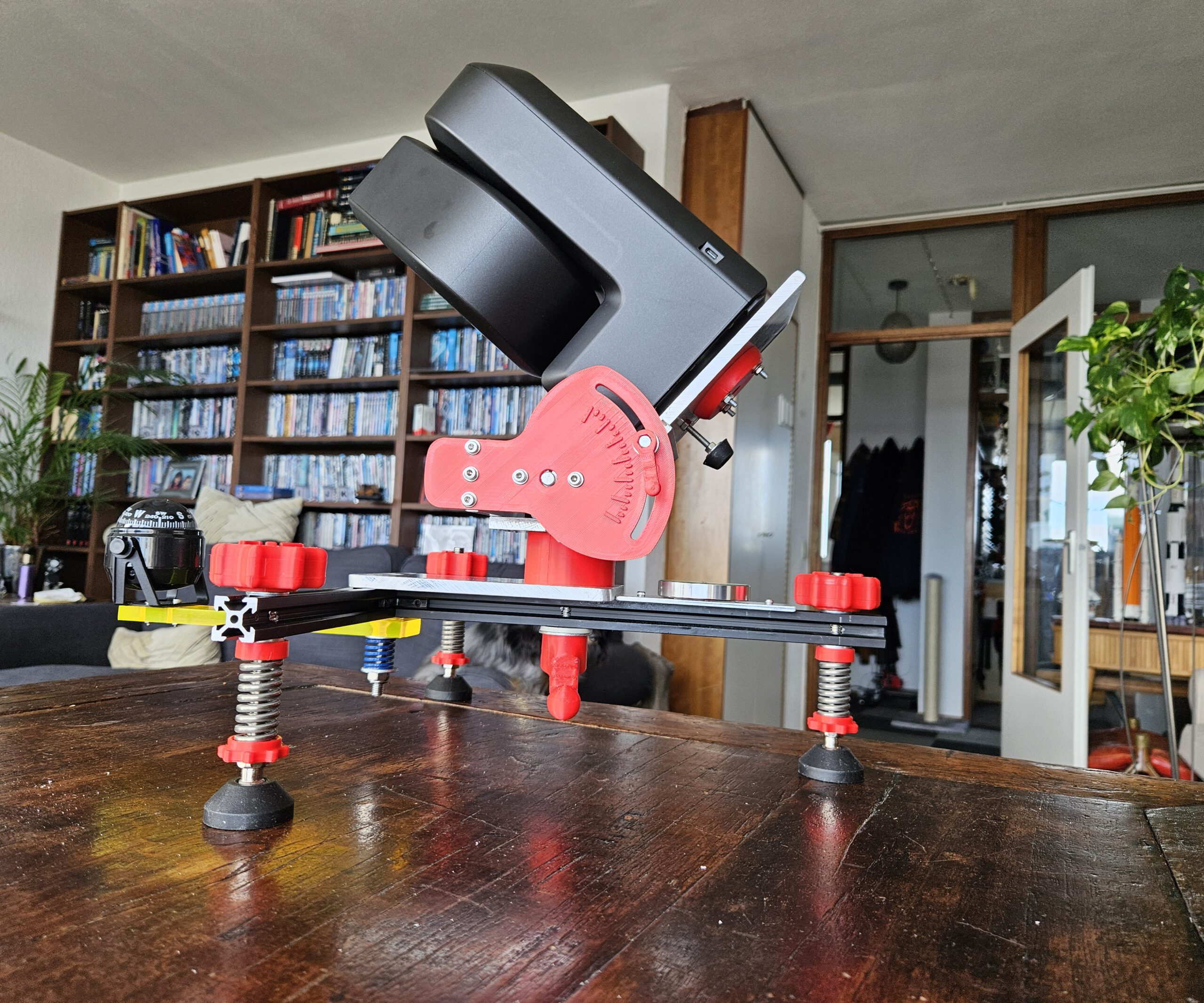
Equatorial Mount for the ZWO Seestar S50 telescope. Giving a smart telescope a different way to follow the sky.

The Seestar S50 is a compact smart telescope capable of automatically locating and tracking objects in the night sky. In its standard configuration it operates as an alt-azimuth telescope, tracking an object by moving in both altitude and azimuth.
That works remarkably well, but the Earth still has an annoying habit of rotating.
For longer observations and astrophotography, an equatorial setup has an important advantage: instead of continuously correcting two axes, the telescope’s primary rotation axis is aligned parallel to the Earth’s rotational axis. Tracking the apparent motion of the sky can then essentially be reduced to rotation around a single axis.
So rather than buying an equatorial wedge or mount, I decided to design and build one specifically for my Seestar S50.


How does it work

The stars appear to move across the night sky because the Earth rotates. Polaris lies very close to the Earth’s rotational axis and therefore appears almost stationary while the other stars seem to circle around it.

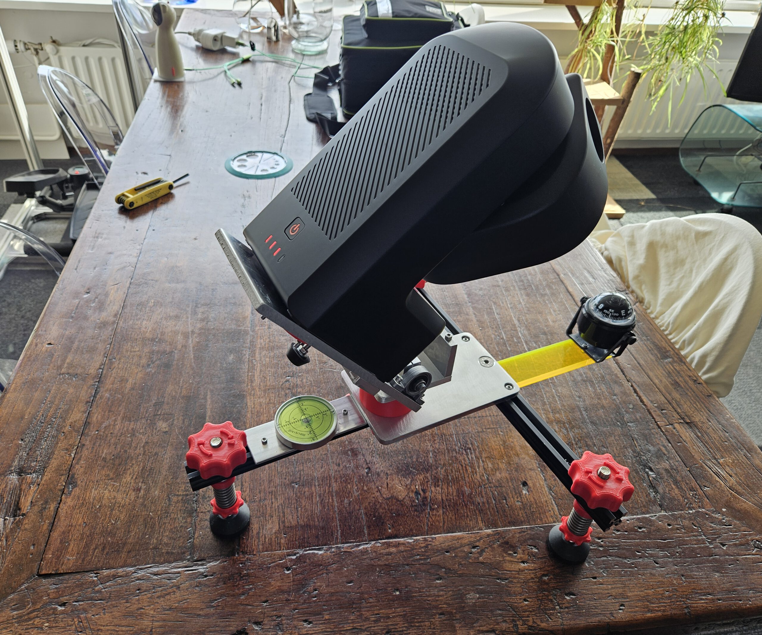
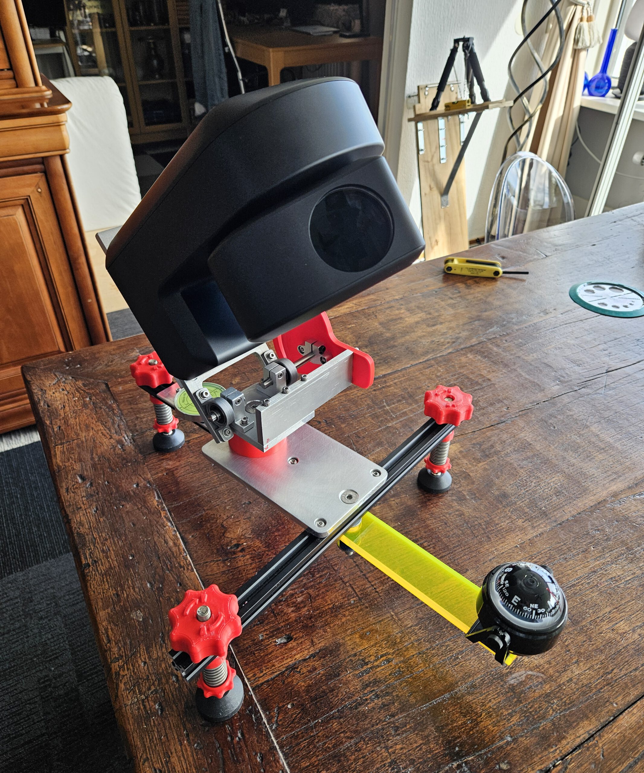
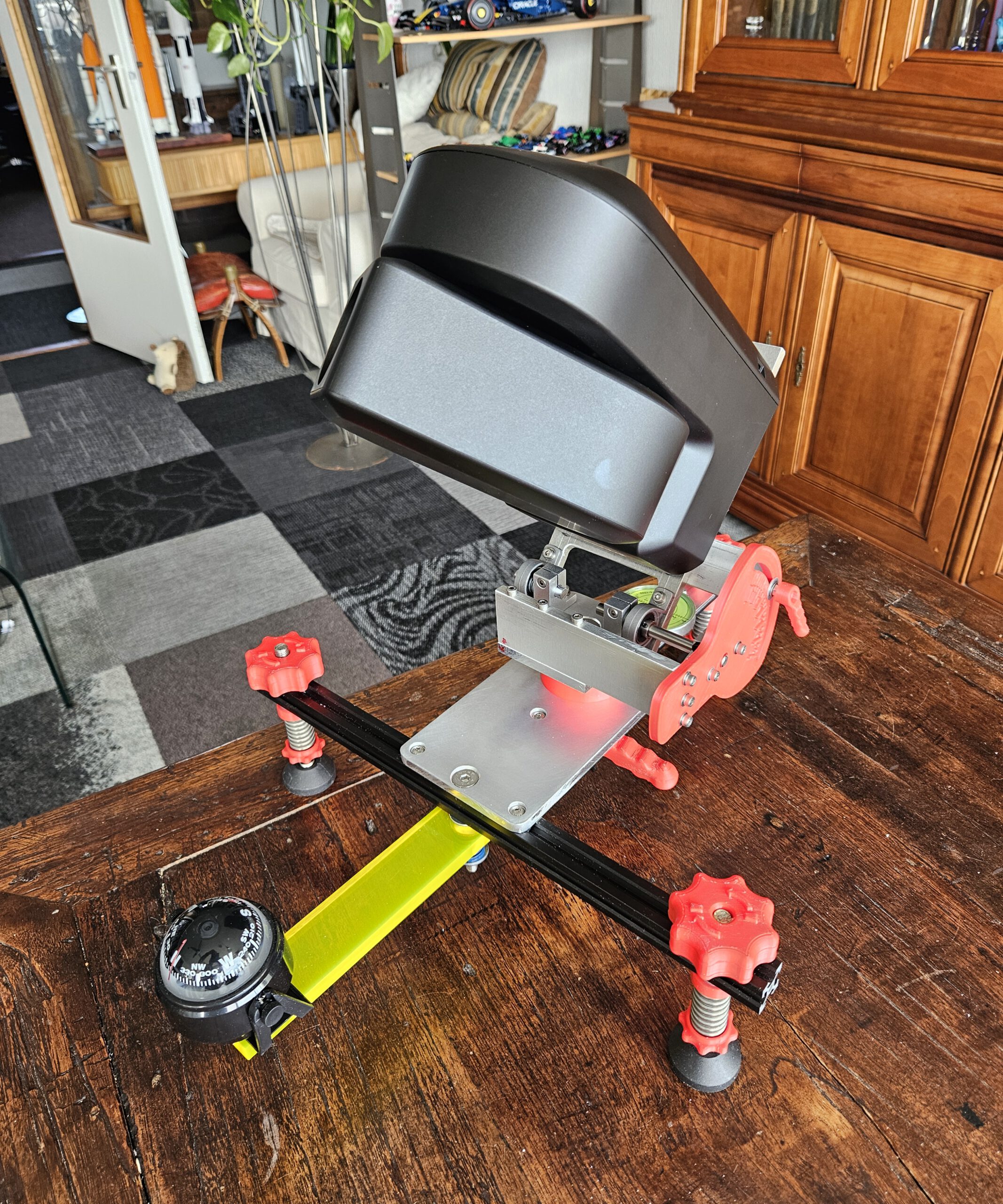
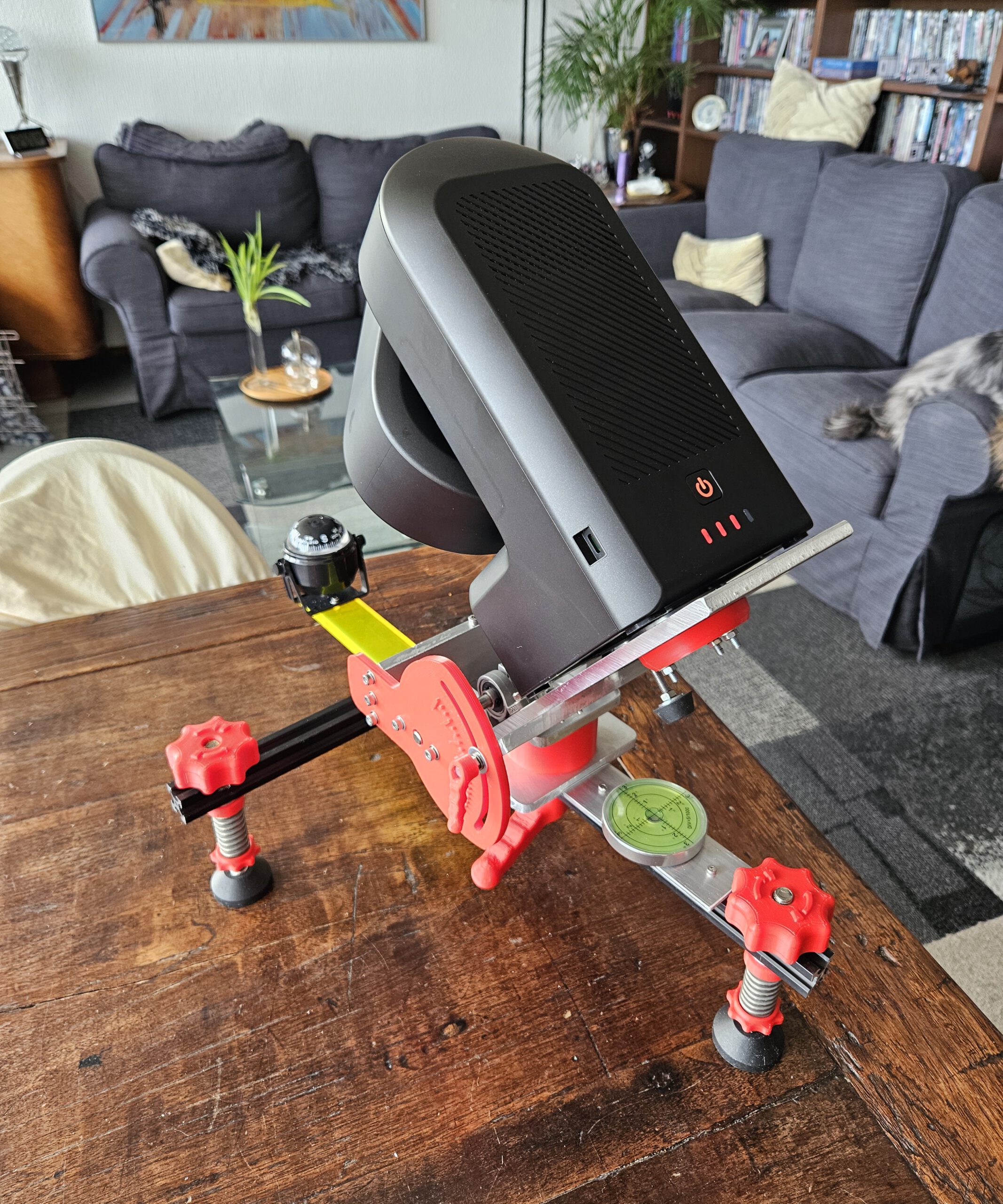
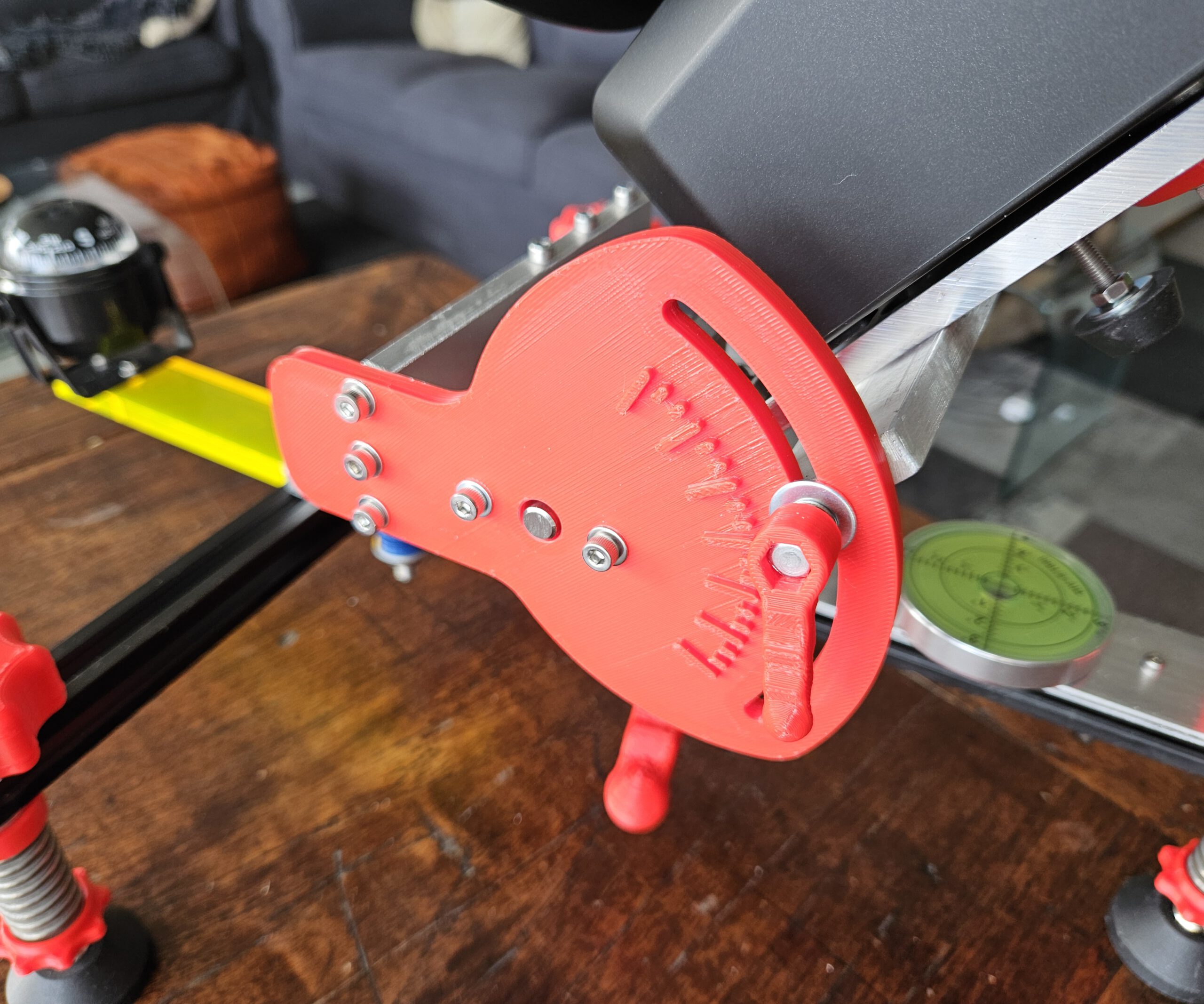
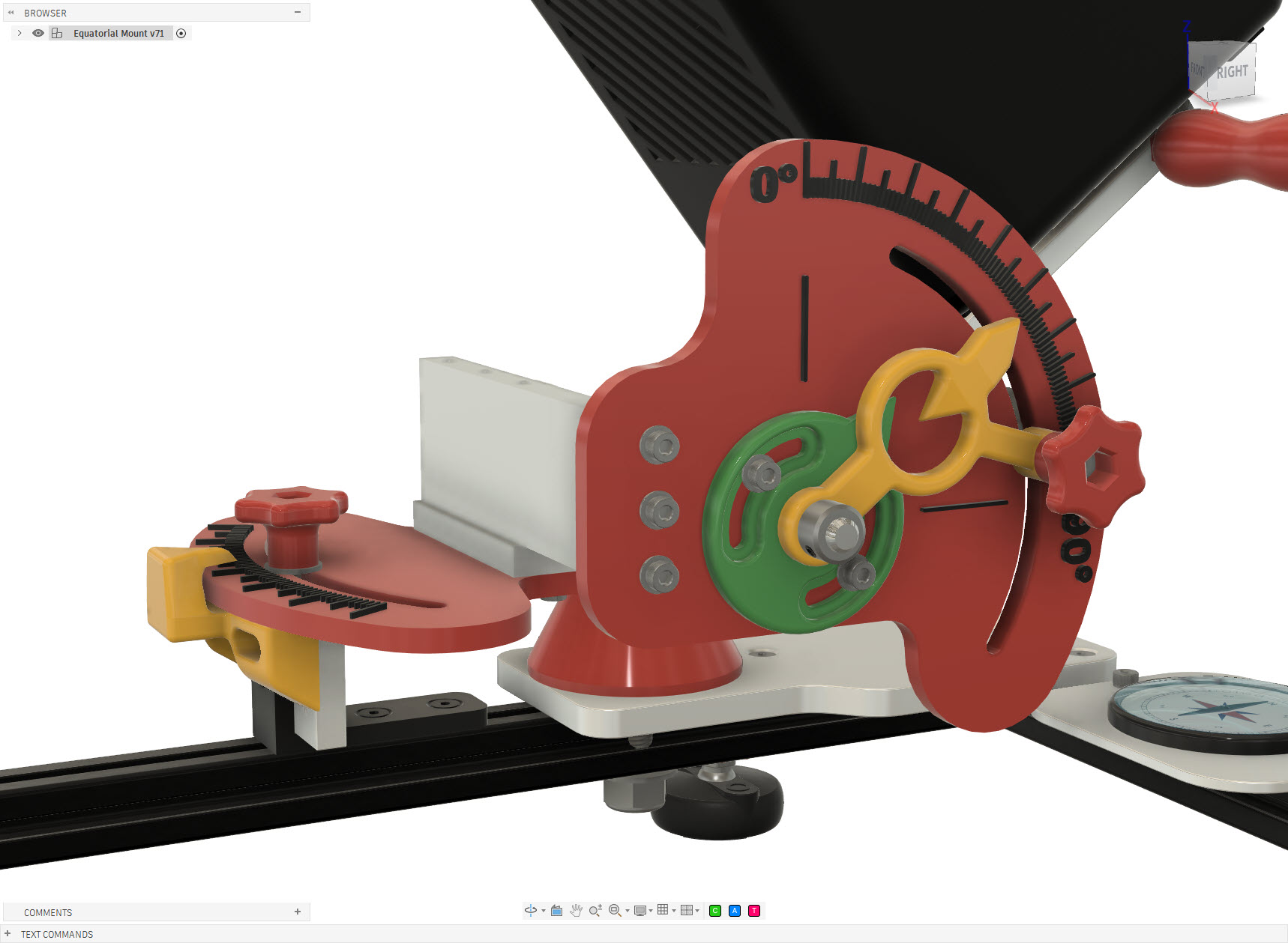
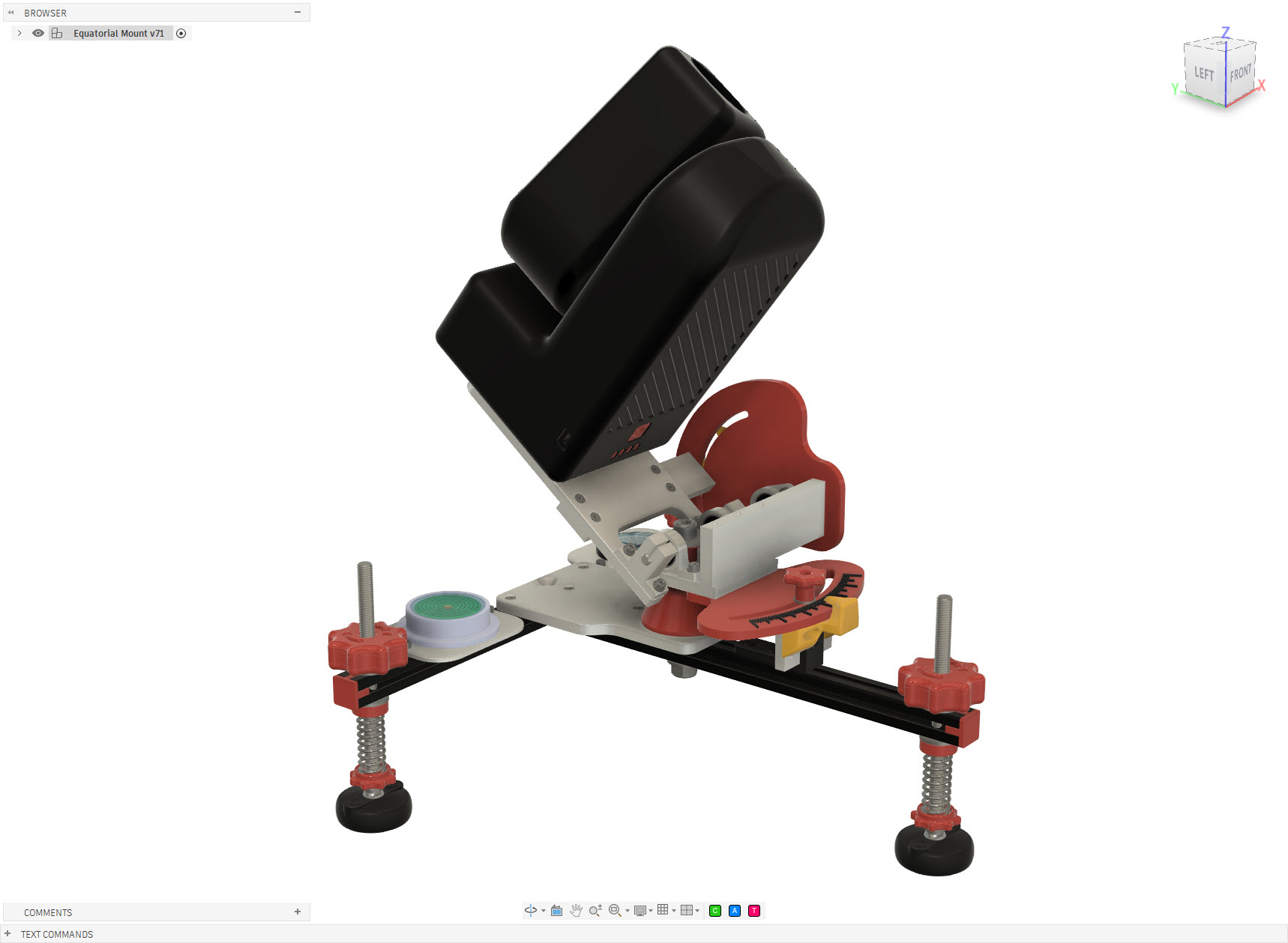
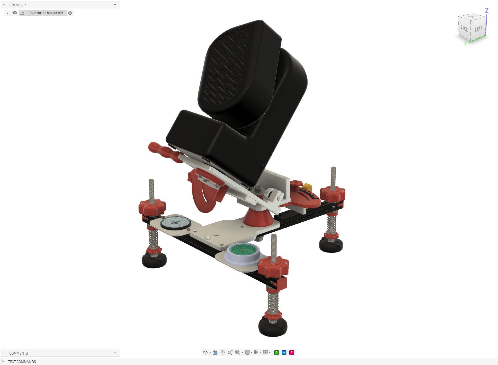
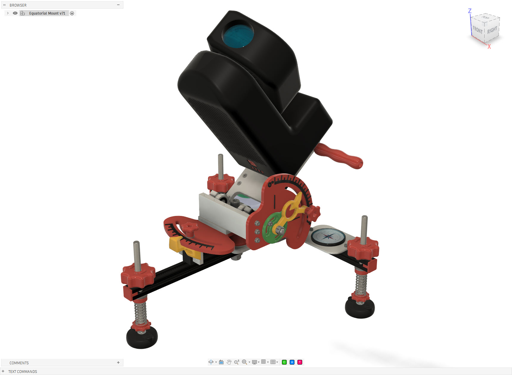
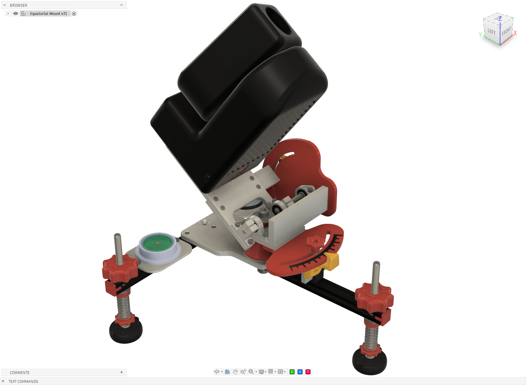
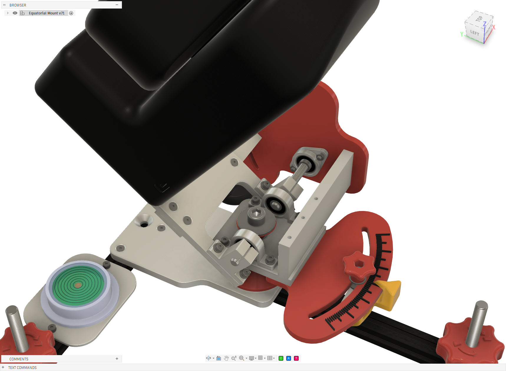
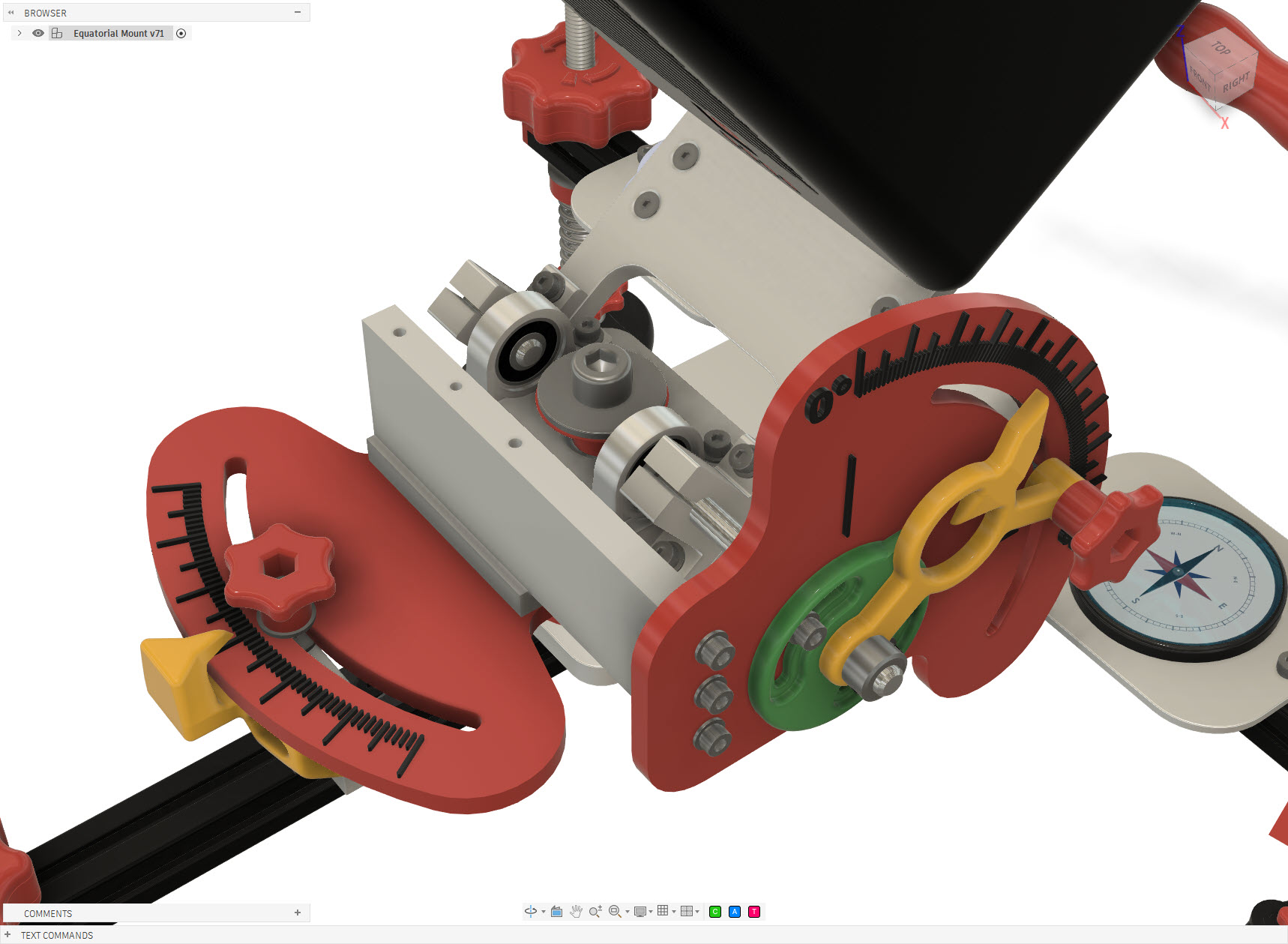
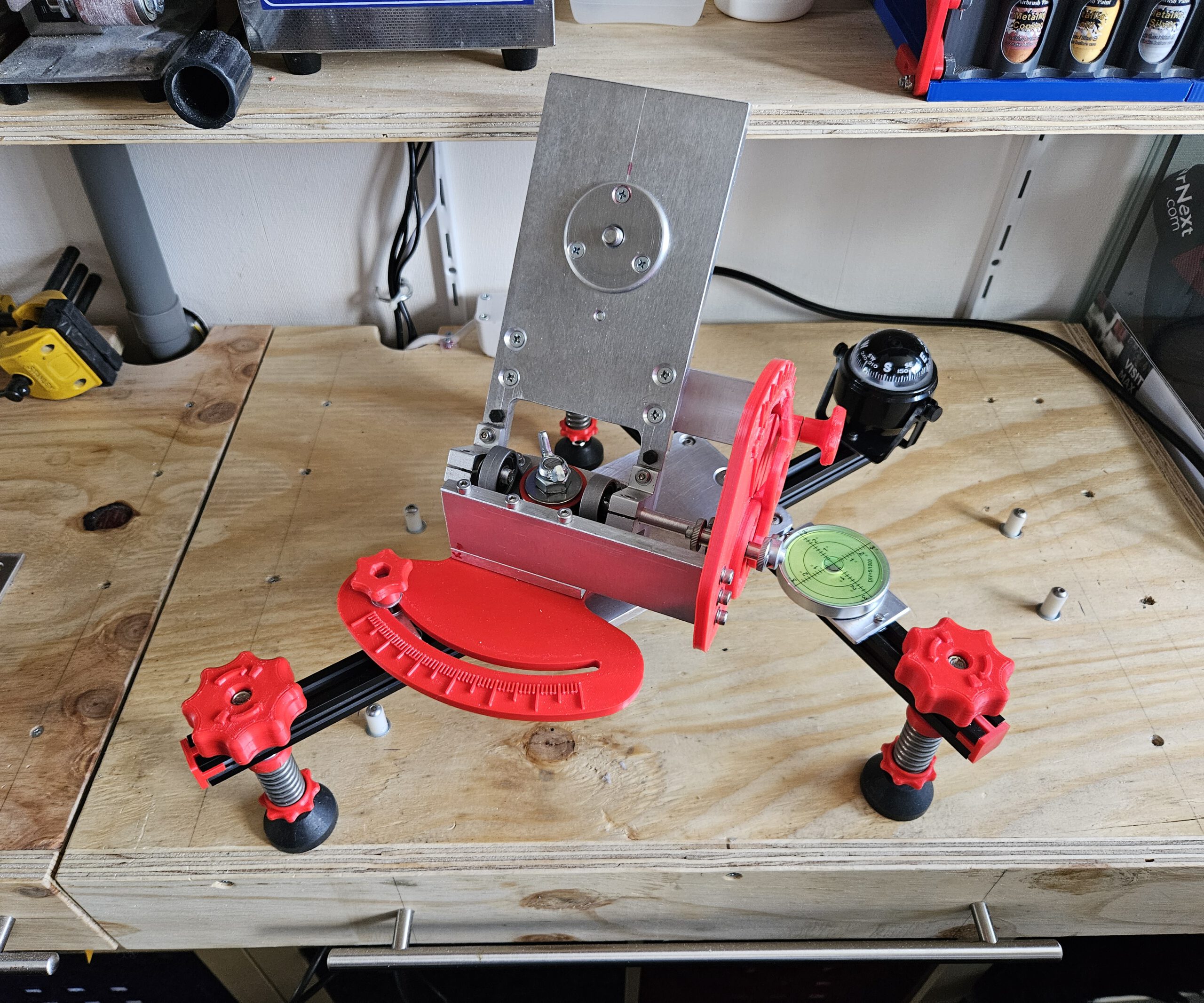
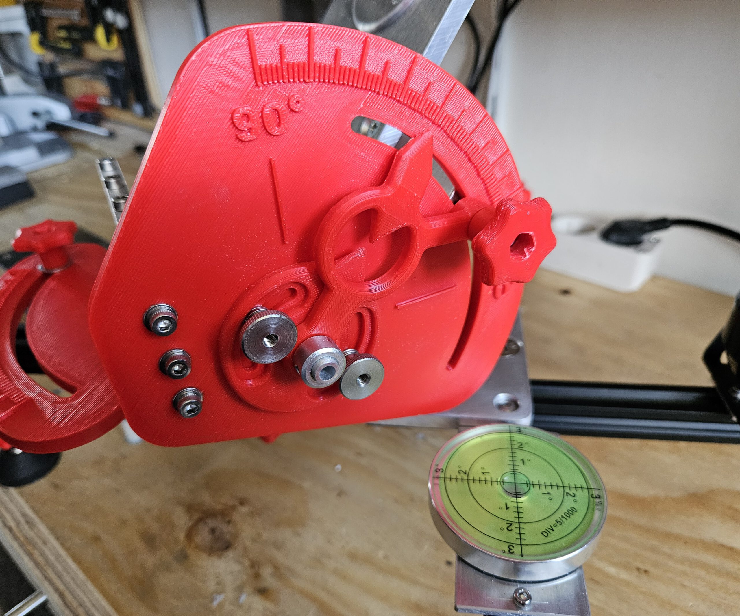
For equatorial tracking, the Seestar’s rotation axis must be aligned parallel to the Earth’s axis. My mount therefore provides adjustment in two directions: altitude sets the angle of the axis to match the local latitude, while azimuth allows the axis to be aimed precisely towards Polaris.

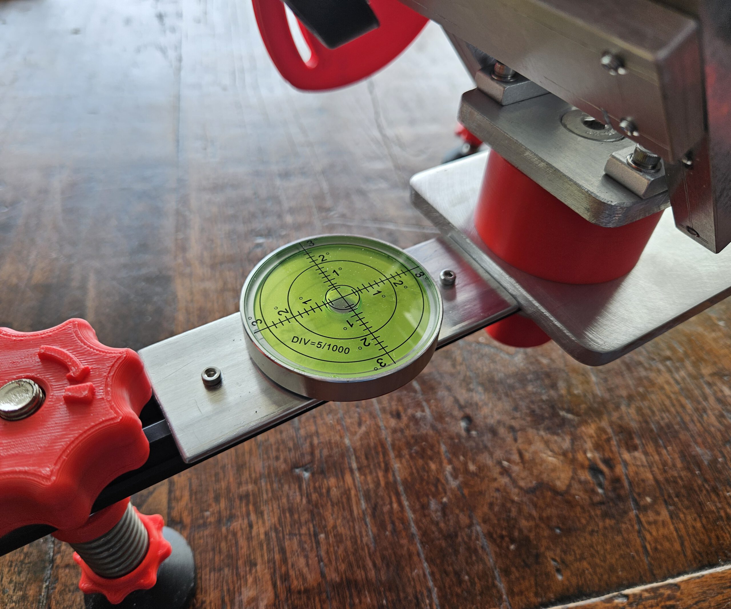
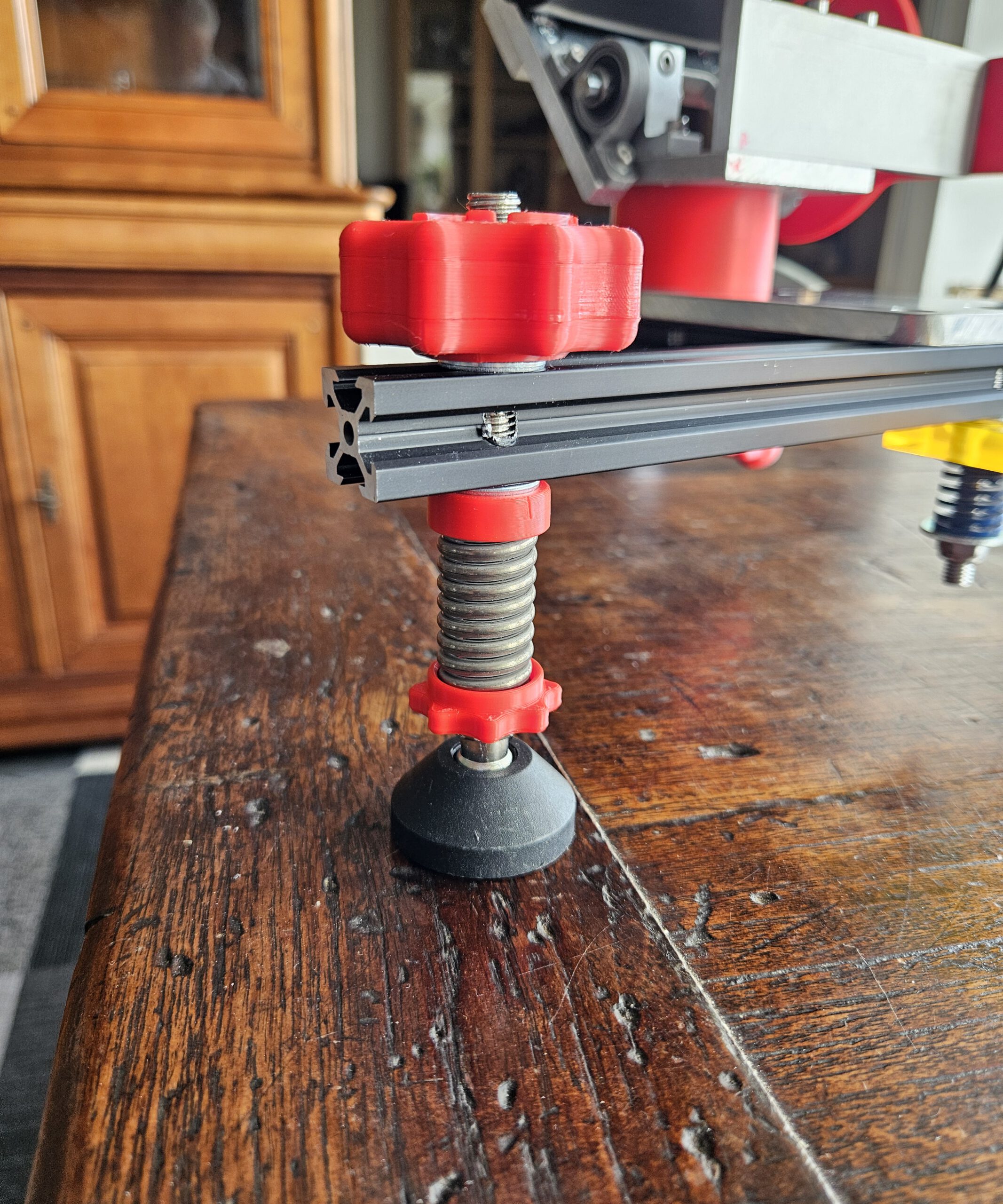
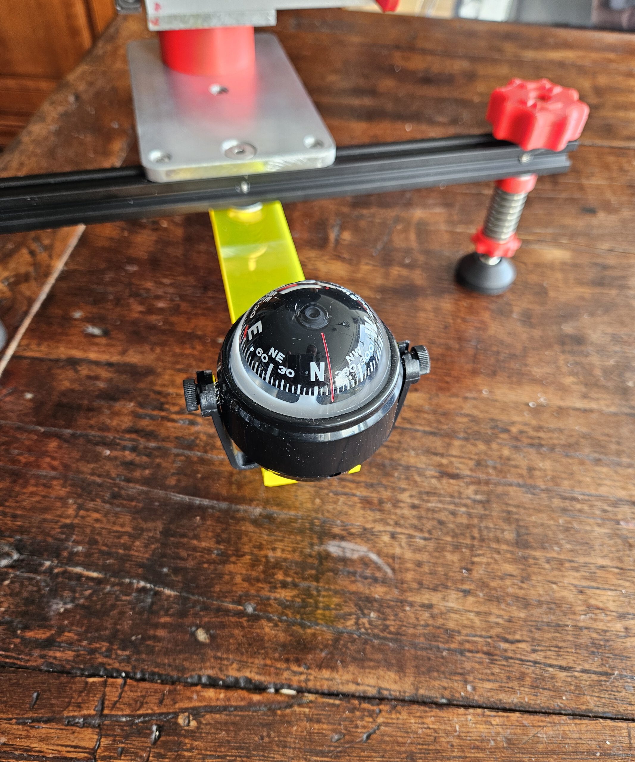
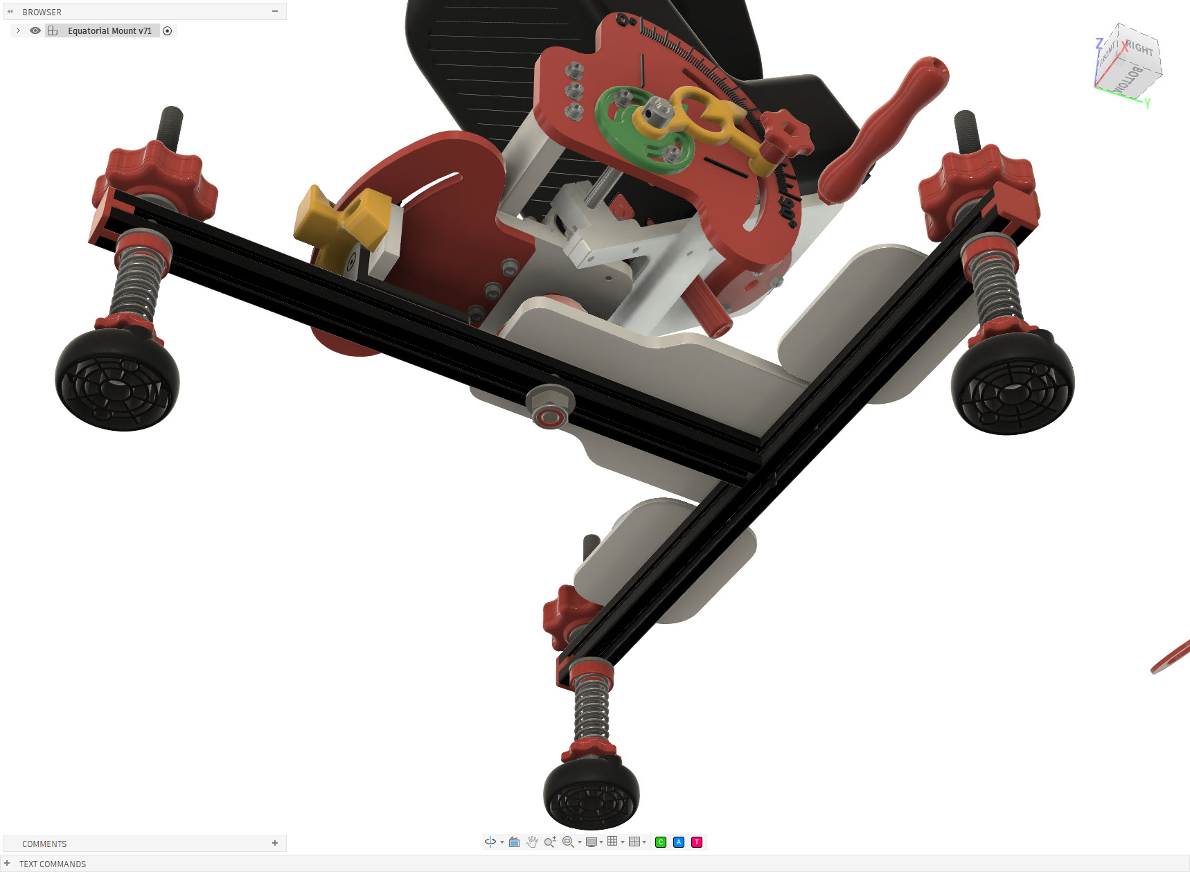
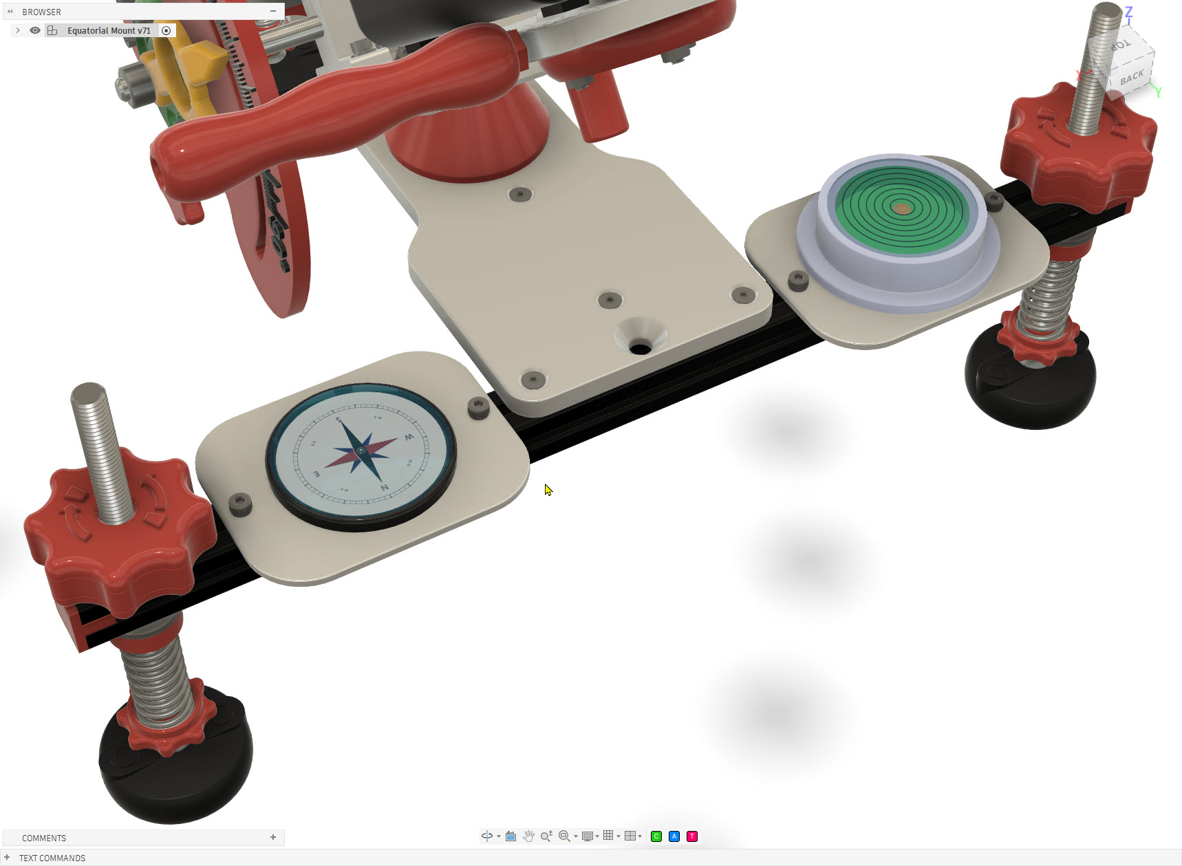
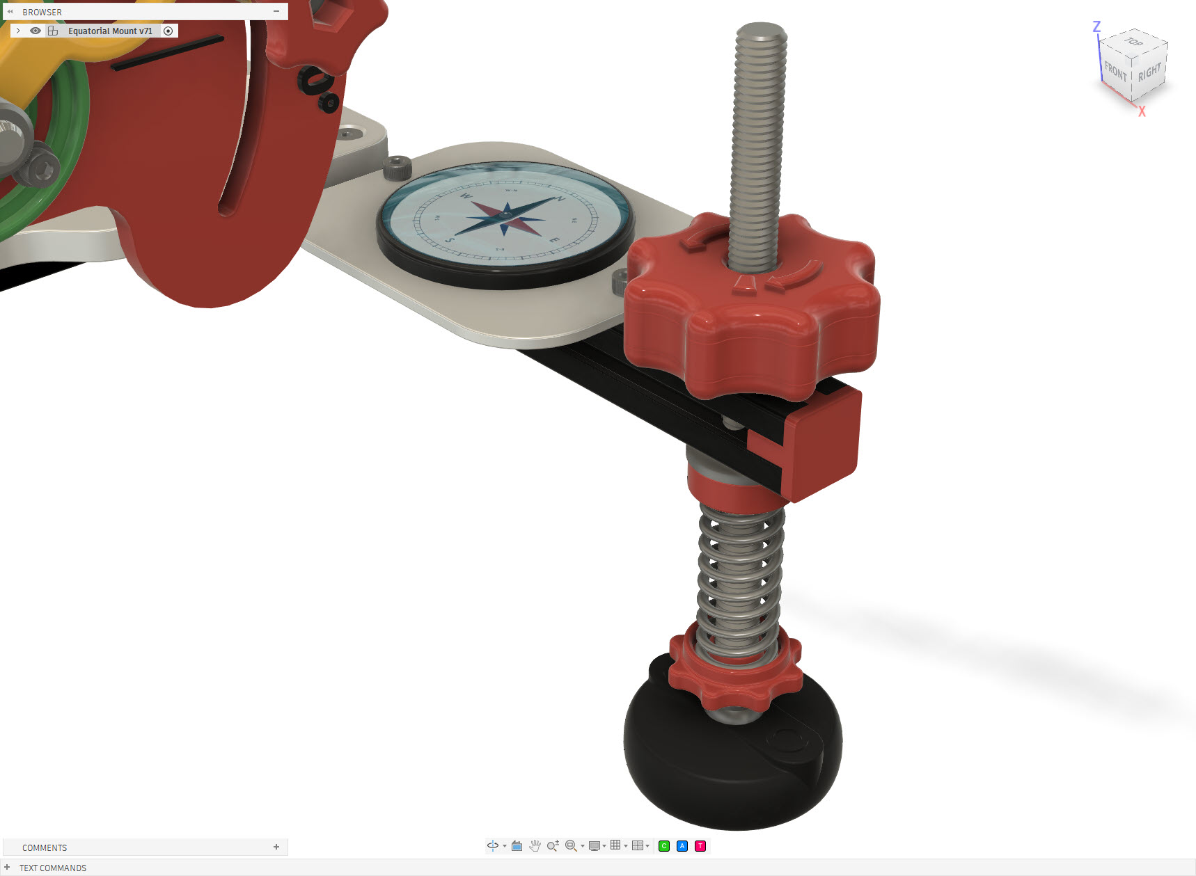
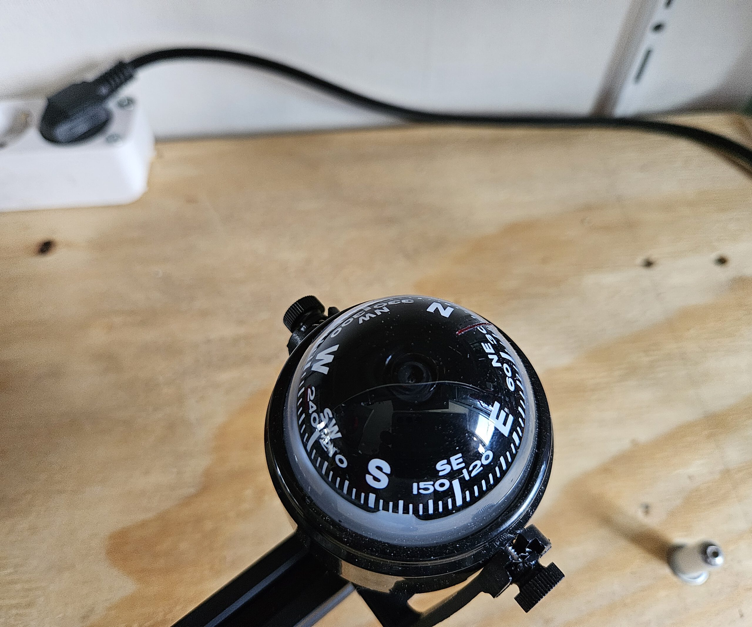
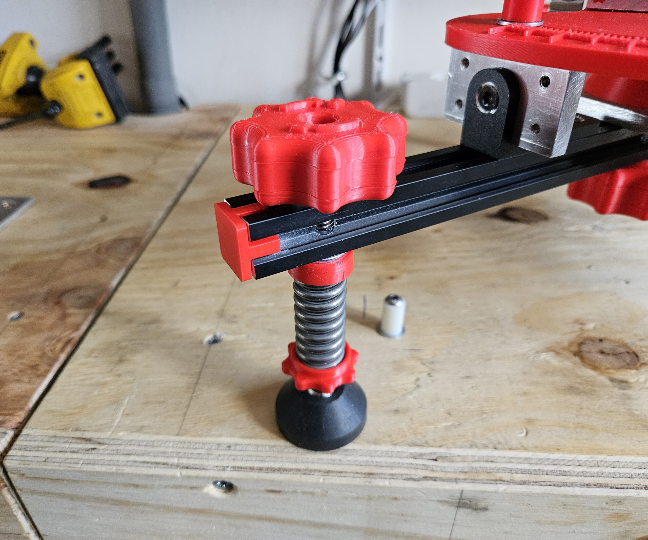
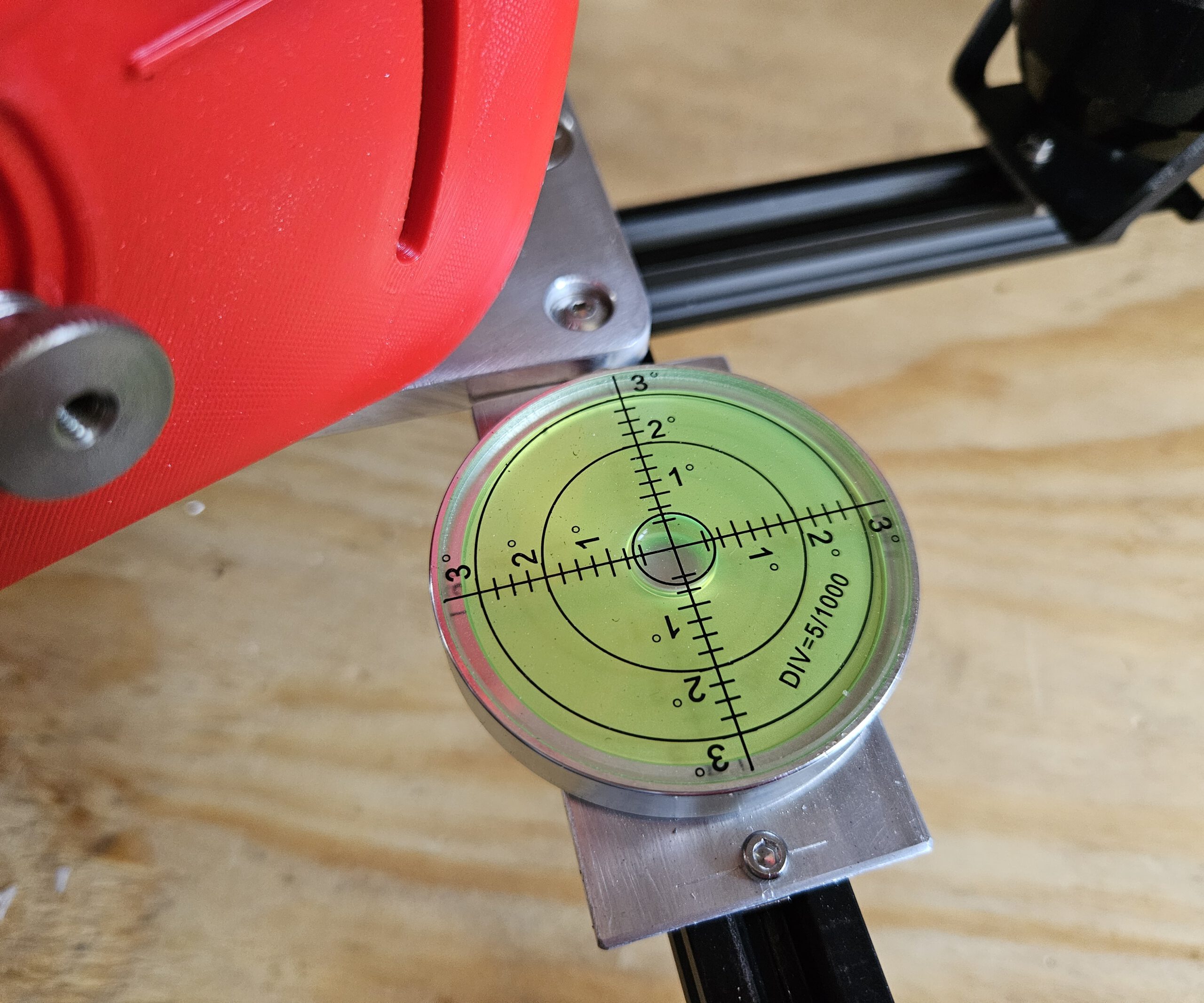
The three adjustable feet are used to level the mount first. A built-in compass and spirit level help with the initial setup, after which the altitude and azimuth controls provide the finer alignment.

Once aligned, the Seestar’s own rotation mechanism can follow the apparent movement of the sky around this axis.

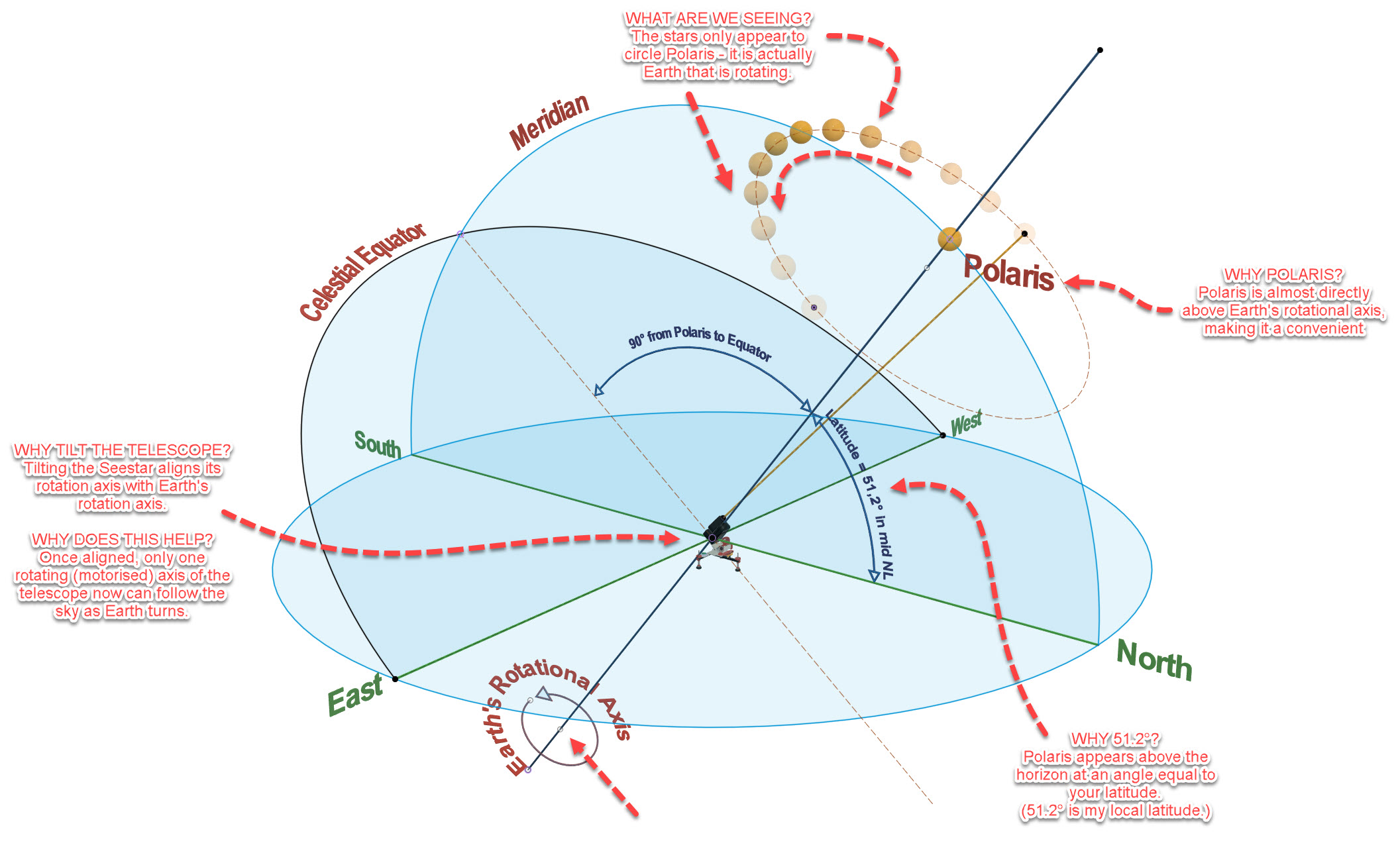
WHY POLARIS?
Polaris is almost directly above Earth’s rotational axis, making it a convenient alignment point.

WHY 51.2°?
Polaris appears above the horizon at an angle equal to your latitude.

WHY TILT THE TELESCOPE?
Tilting the Seestar aligns its rotation axis with Earth’s rotation axis.

WHY DOES THIS HELP?
Once aligned, one rotating axis can follow the sky as Earth turns.

En eventueel bij het rijtje sterren bovenaan, omdat dát volgens mij voor een leek de grootste aha oplevert:

WHAT ARE WE SEEING?
The stars only appear to circle Polaris — it is actually Earth that is rotating.


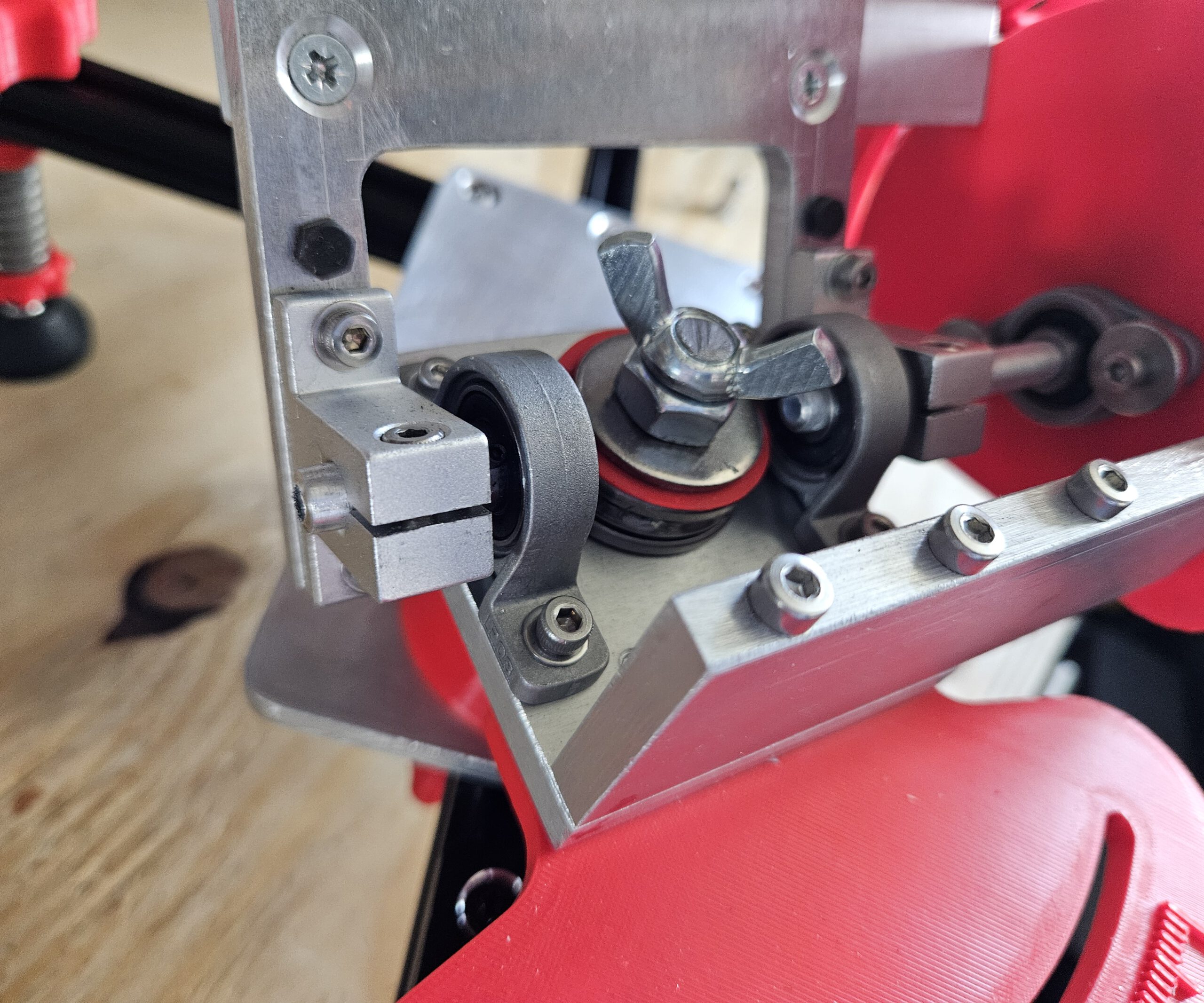
Pictures of the design


Design drawings for the Aluminium parts

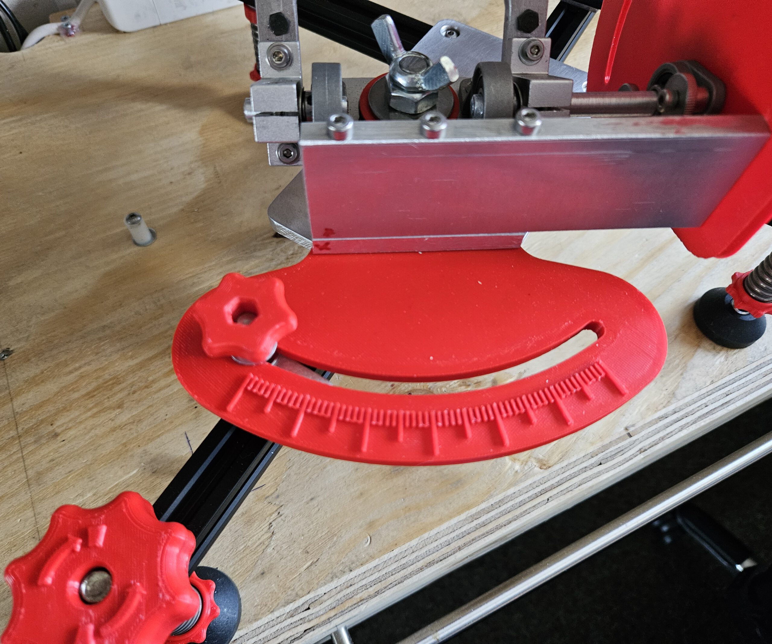
The scales can be printed, but please use ABS or Nylon for stability. The other parts:

  • Azimuth Platform
  • Equatorial Mount
  • Rotaton Plate

Must be made from metal for stability. I used easy to work thick Aluminium plates. Back then I worked it by hand and hand tools. Nowadays I woult put it in mij CNC milling machine. But some old fashion workmanship will do too.


Bill Of Materials (BOM)

Tripod Leg BOM

QtyComponentSpecification / Notes3D printed
1Compression Spring3.4 × 20 × 50 mm, 30 kgn/a
1Pivot Head BoltM10 × 100n/a
1Rubber FootWeather-resistantn/a
3WasherM10, OD 12.5 mmn/a
1NutM10n/a
1Spring Capn/aABS/Nylon
3Doweln/aABS/Nylon
1Thumbwheel Bottomn/aABS/Nylon
1Thumbwheel Middlen/aABS/Nylon
1Thumbwheel Topn/aABS/Nylon
1Spring Thumbwheeln/aABS/Nylon
1Spring Capn/aABS/Nylon

Quantities shown are for one tripod leg. Three identical legs are required for the complete mount.

Base Platform BOM

QtyComponentSpecification / Notes3D printed
1Aluminium Plate220 × 100 × 8 mmn/a
1WasherM10n/a
1LocknutM10n/a
5Flat Head Hex BoltM4 × 30n/a
1Socket Head BoltM10 × 120n/a
1APS Lockn/aABS/Nylon
1Top Azimuth Supportn/aABS/Nylon
1Bottom Azimuth Supportn/aXABS/Nylon

Altitude Platform BOM

QtyComponentSpecification / Notes3D printed
1Aluminium Plate205.2 × 100 × 8 mmn/a
1Lens Head Bolt3/8″-16 × 3/4″n/a
1External-Tooth Lock Washer3/4″n/a
2Flat Head Hex BoltM4 × 30n/a
4Flat Head Hex BoltM4 × 14n/a
1Hex BoltM4 × 15n/a
1Hex BoltM4 × 40n/a
1Socket Head BoltM4 × 30n/a
4Socket Head BoltM4 × 13n/a
3Hex NutM4n/a
15WasherM4n/a
1Steel AxleØ8 mm × 100 mmn/a
1Steel AxleØ8 mm × 30 mmn/a
1Shaft CollarID 8 mm, OD 14 mm, H 8 mmn/a
1Cup Point Hex Set ScrewM4 × 3n/a
2SK8 Axle Support42 × 32 × 14 mm, ID 8 mmn/a
1Adjustable Handle Block Altn/aABS/Nylon
1Alt Gripn/aABS/Nylon
1Aluminium Turning Basen/aABS/Nylon
1Alt Platform 0 Degree Supportn/aABS/Nylon
1Scale Pointern/aAny
1Thumb Screwn/aAny
1Placeholder for Lens Head Boltn/aAny

Azimuth Platform BOM

QtyComponentSpecification / Notes3D printed
4Flat Head BoltM4 × 20n/a
3Roll Bearing Block42 × 32 × 14 mm, ID 8 mmn/a
8Socket Head BoltM4 × 13n/a
8WasherM4n/a
2Socket Head BoltM4 × 13, additional hardwaren/a
2NutM3n/a
2SKF 51203 Thrust Bearing51203 / S1203 XCn/a
1Azimuth Scale & Lockn/aABS/Nylon
1Altitude Lock Plate V5n/aABS Nylon
1Lockable Home Altitude Pointern/aAny
1Adjustable Handle Block Azin/aABS/Nylon

And then came the ultimate field test: a solar eclipse.

With the mount polar-aligned and the Seestar tracking the Sun, I could leave the telescope to follow the event instead of repeatedly repositioning it by hand. The result was a complete time-lapse of the eclipse — and, more importantly from a maker’s perspective, proof that the design actually worked outside Fusion 360.
Towards the end of the solar eclipse clip, the image starts to shift. This happened because the telescope eventually ran into the window frame without me noticing. A bit unfortunate, but it is what it is. Apart from that, the recording was successful and the mount did exactly what it was supposed to do.

Walkin’ Pets Dog Wheelchair Modifications

Making a great dog wheelchair work better for a very small dog

Sometimes you buy a well-designed product, use it for a while, and discover that for your particular situation it could use just a little improvement.

And sometimes “a little improvement” somehow turns into recreating half the thing in CAD, designing a suspension system, adding ball bearings, printing custom parts and rebuilding the rear end.

This was one of those times.

Our dachshund suffered a herniated disc that left his left hind leg almost completely paralyzed and significantly reduced the control of his other hind leg. Indoors he adapted remarkably well and could get around mostly using three legs. Outside, however, that only worked for short distances.

To give him more freedom, we bought a Walkin’ Pets Dog Wheelchair. Pls see https://walkinpets.com/. It is a solid, well-made product and gave him the opportunity to walk outside again.

But because he is a small dachshund — with a long back that had already been injured — I soon noticed a few things that could be improved specifically for him.

The problems

The first problem was rolling resistance.

For a larger dog, the resistance of the original wheels probably isn’t particularly significant. For a small dachshund, however, every bit of additional resistance matters. He had to work noticeably harder to pull the wheelchair along.

The second problem was rigidity.

The original construction keeps the wheels firmly positioned relative to the frame. That’s normally exactly what you want, but in his case bumps, uneven pavement and stepping off a curb transferred movement directly through the wheelchair.

Because of his back injury, he compensated for this by walking rather stiffly.

The third problem appeared around doorways and other obstacles.

Take a corner just a little too tightly and a wheel can catch the door frame. Instead of sliding past the obstacle, the wheelchair suddenly stops or jerks sideways.

Again: not particularly pleasant when the passenger happens to have a bad back.

So…

CAD time.

Rebuilding the wheel assembly

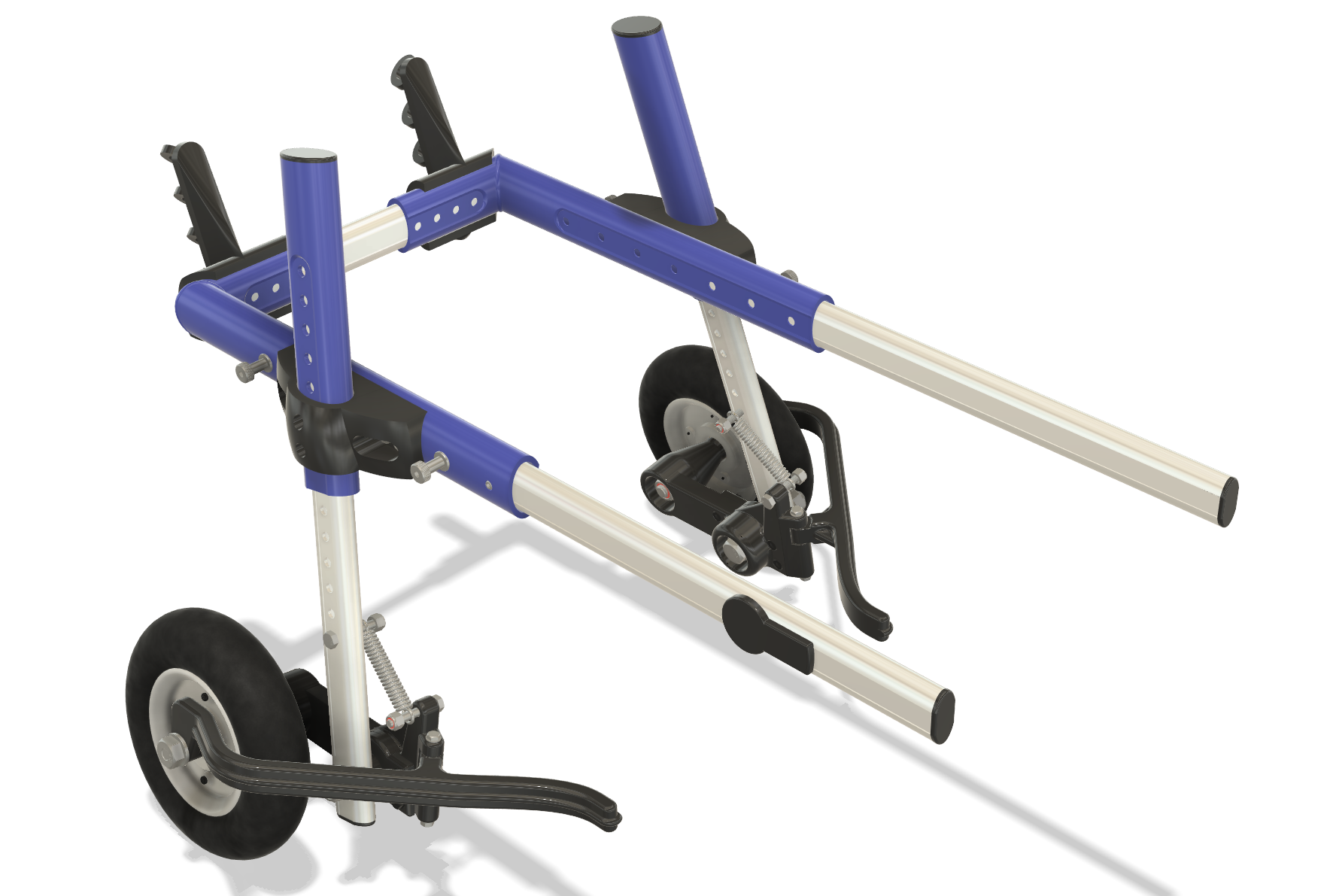
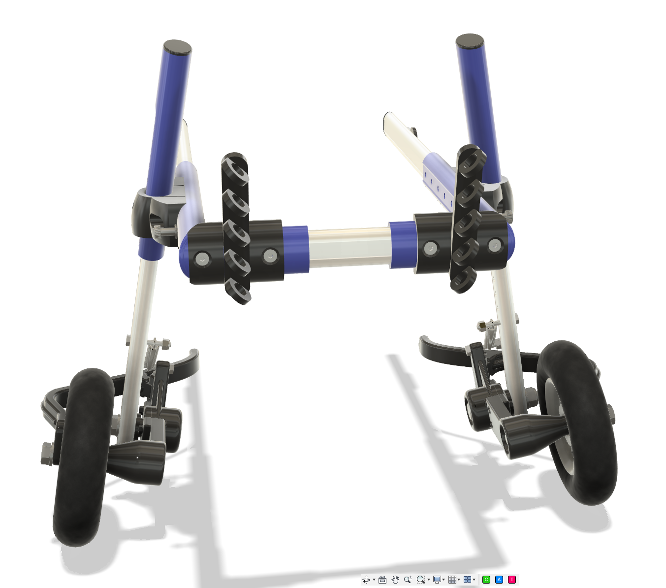
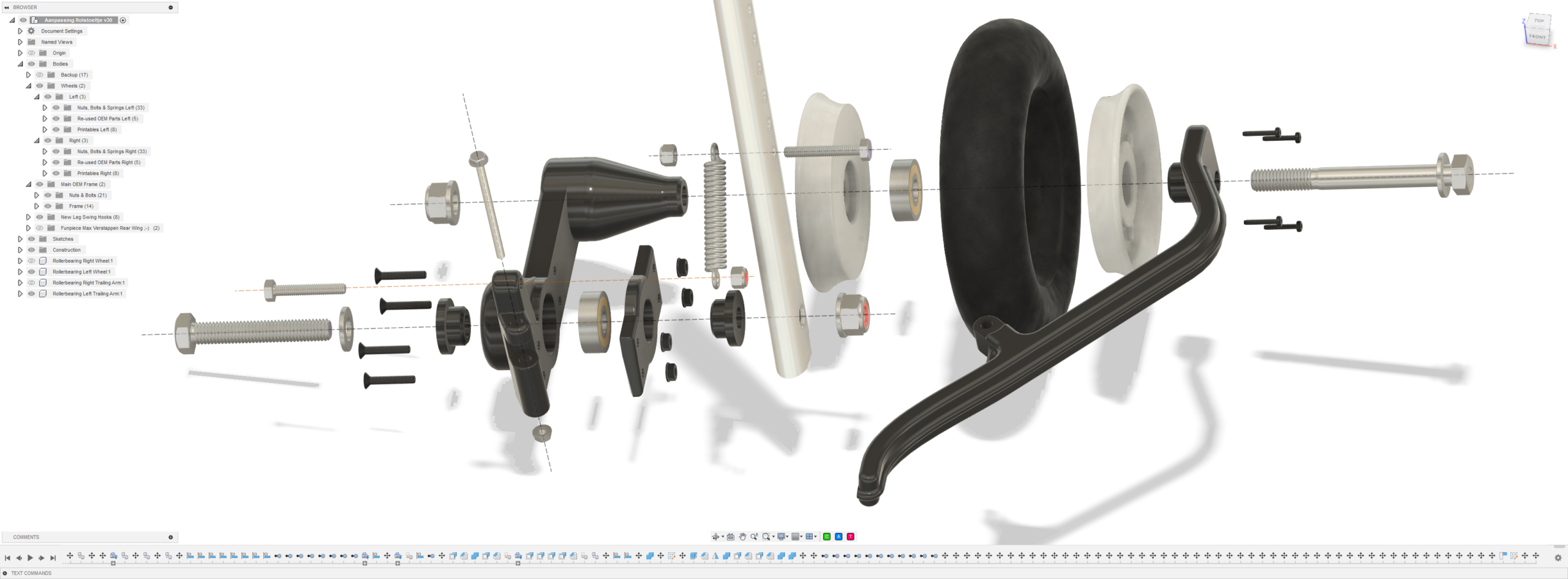
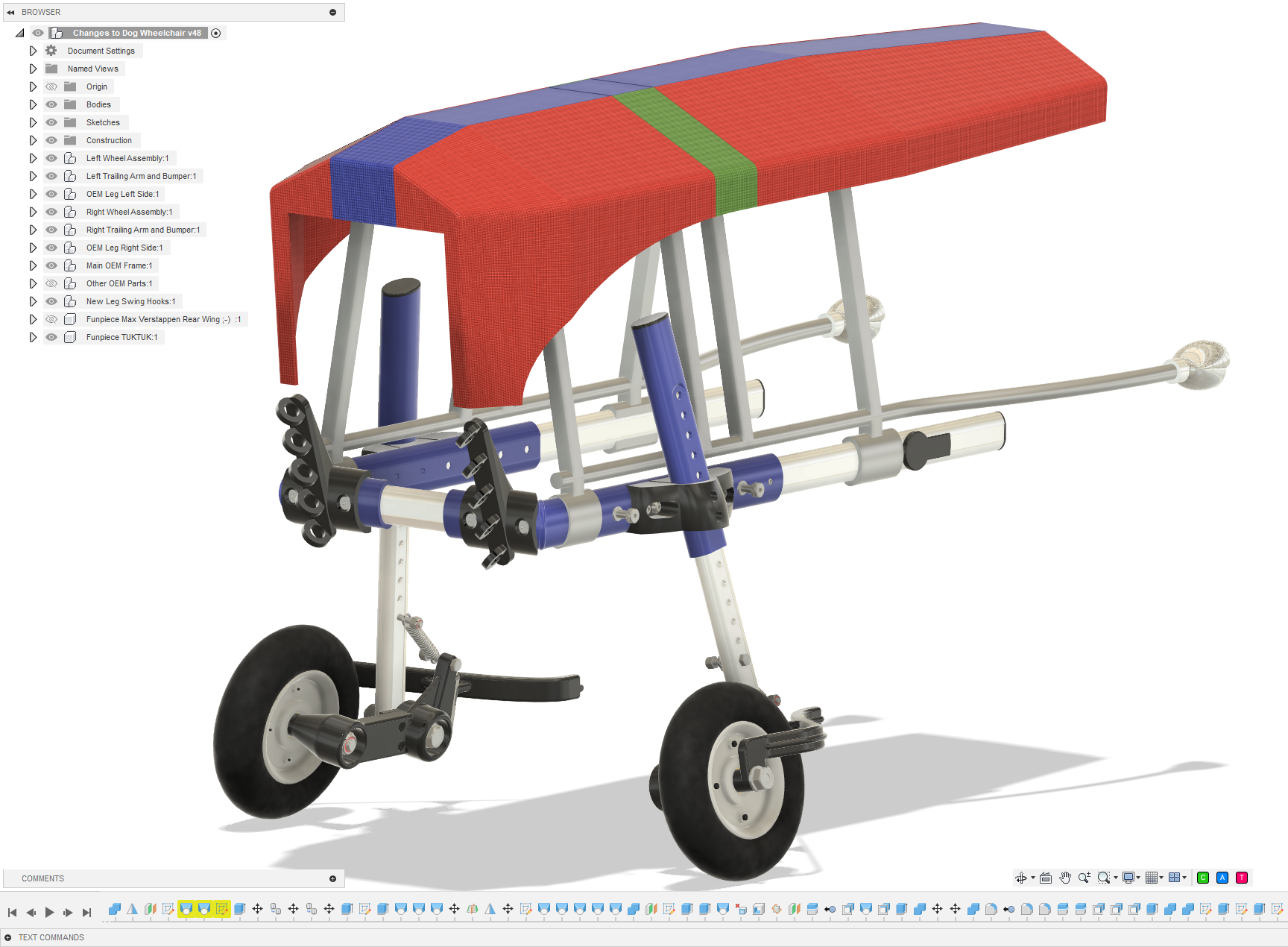
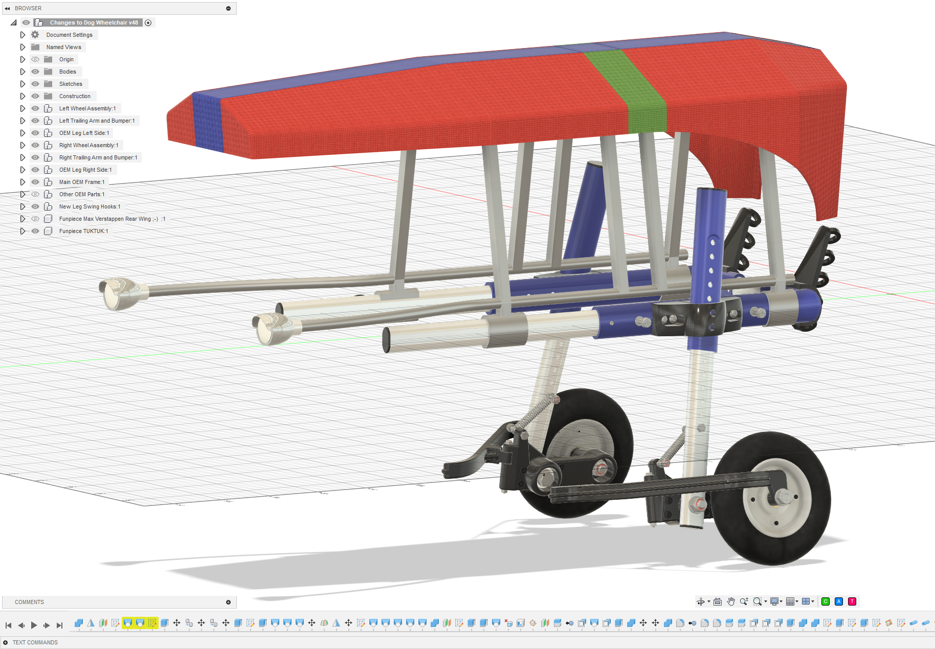
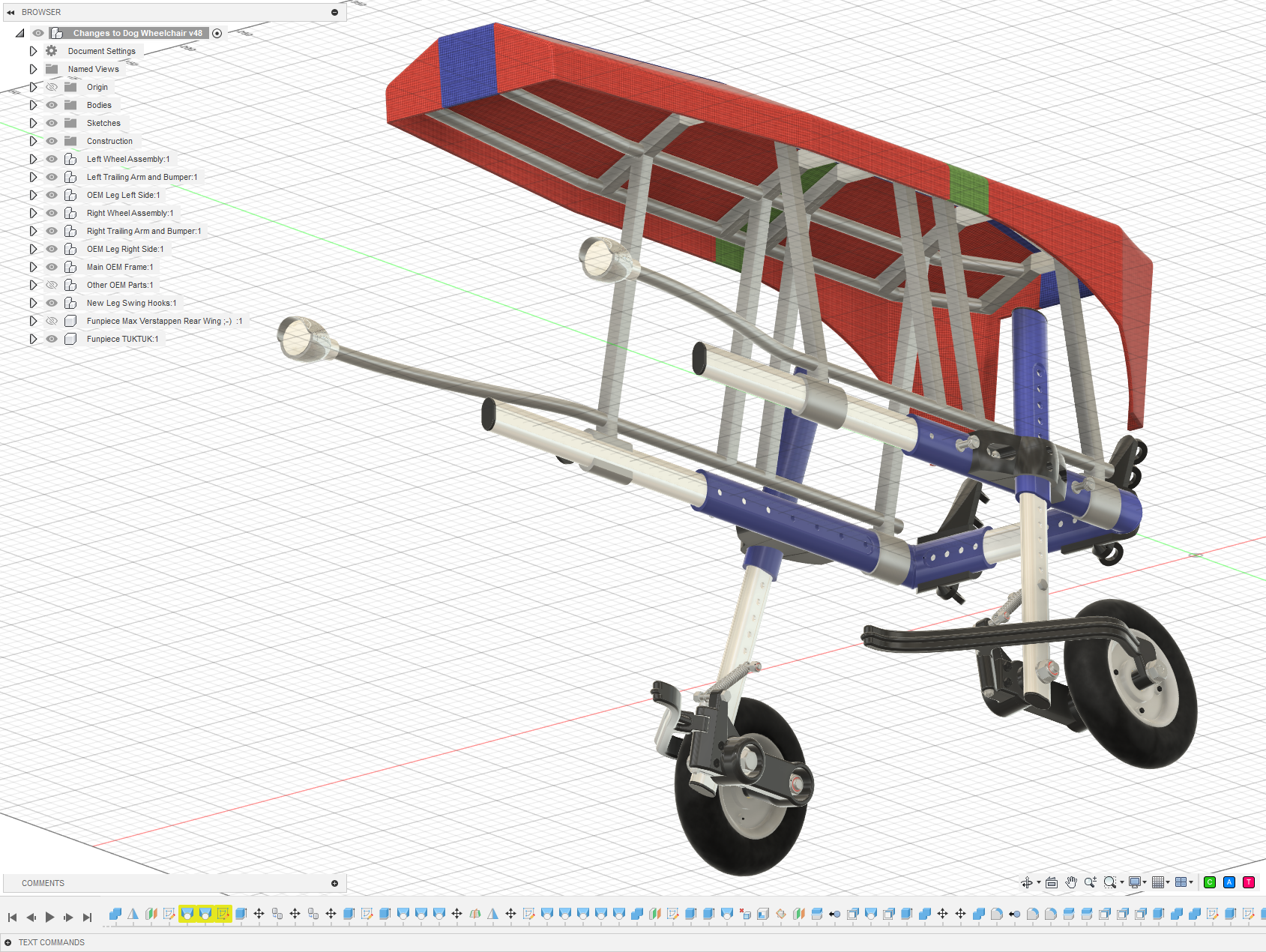
I recreated the relevant parts of the wheelchair in 3D and started experimenting with alternative wheel assemblies.

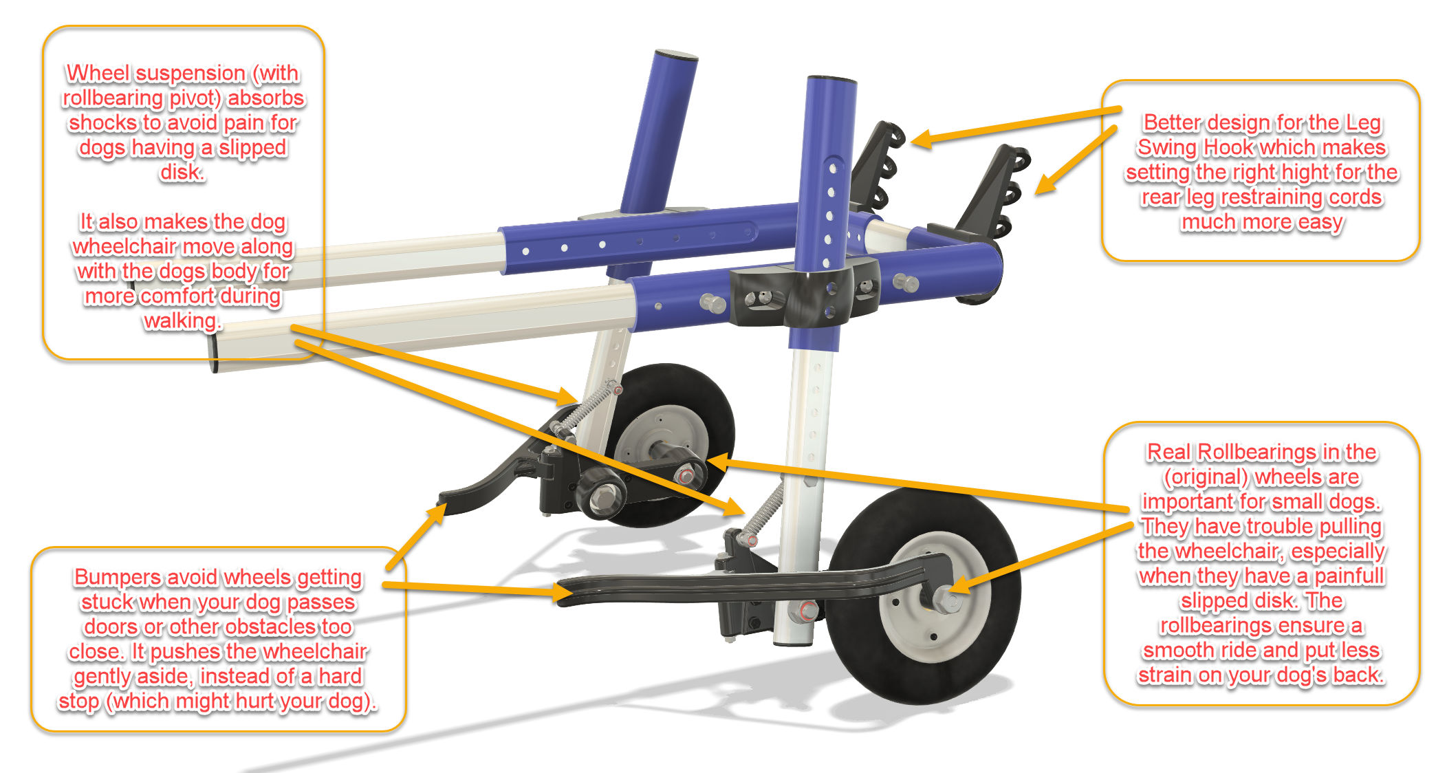
The eventual design combines three modifications:

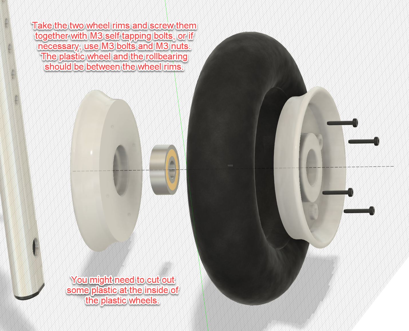
Ball-bearing wheels

The original wheels were modified to run on proper ball bearings.

This considerably reduced the rolling resistance. For a small dog this makes a surprisingly large difference: less effort is needed simply to keep the wheelchair moving.

The improvement was immediately noticeable during walks.

Independent trailing-arm suspension

This became the largest part of the modification.

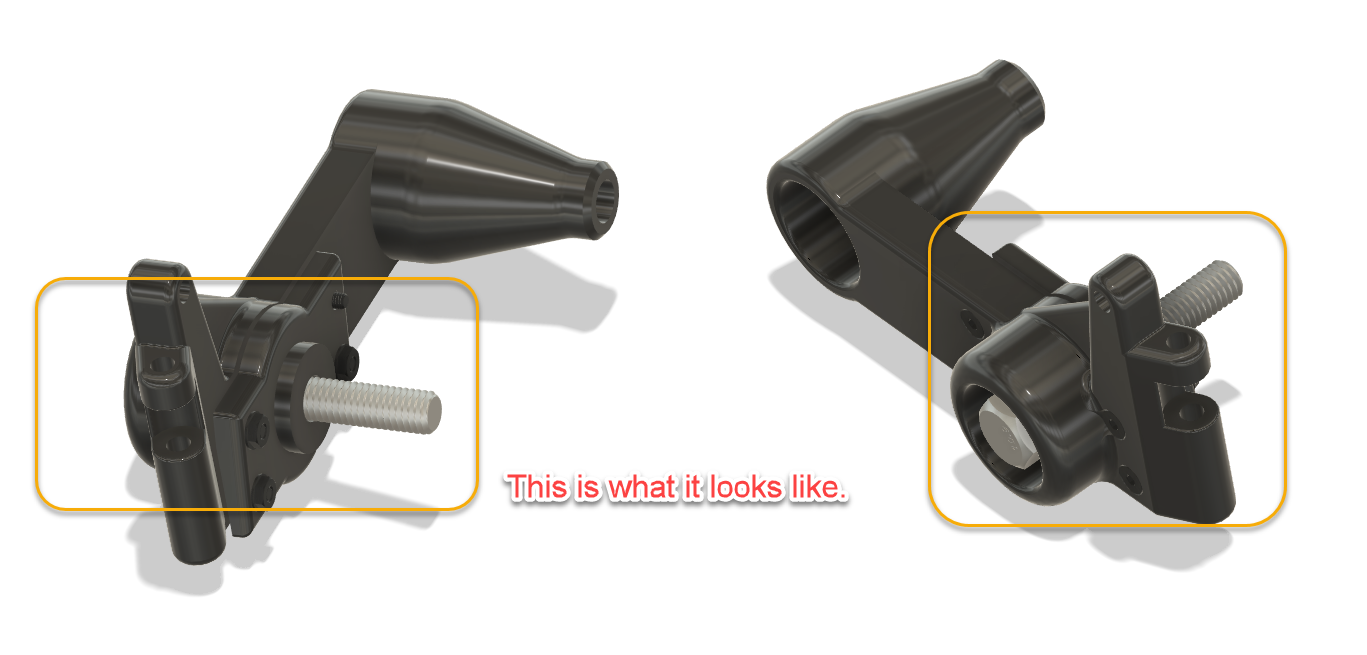
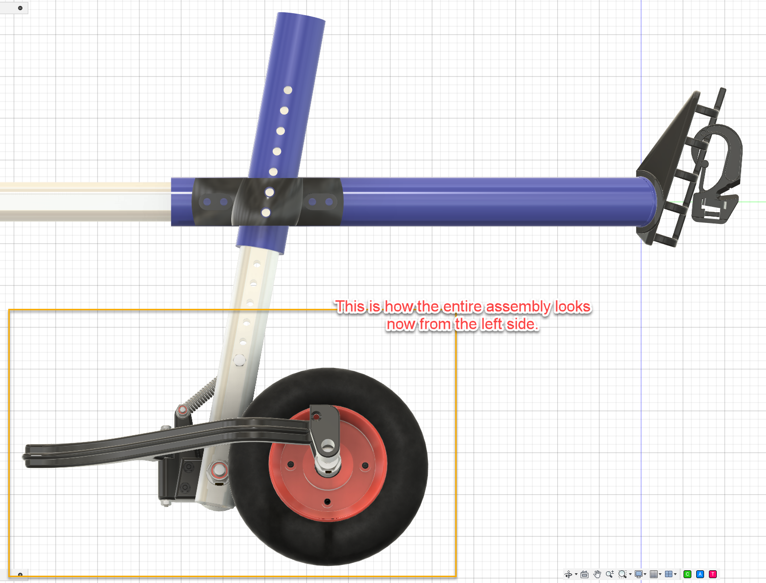
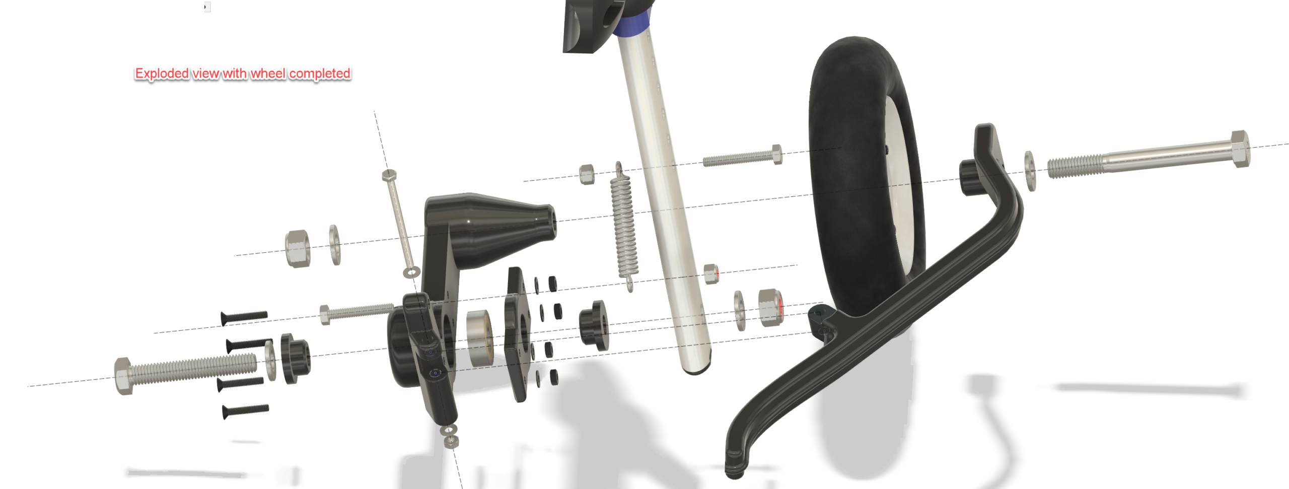
Each wheel is mounted on a pivoting trailing arm running on a ball bearing. A spring between the trailing arm and the wheelchair leg provides suspension.

Instead of every bump being transmitted directly into the frame, the wheel can now move independently.

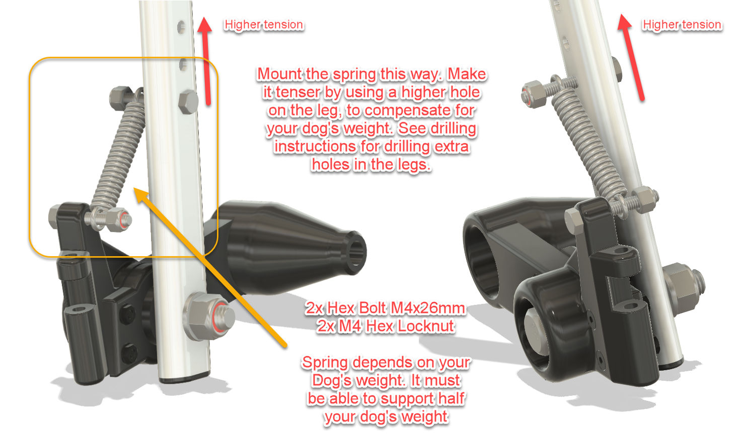
The spring preload can be adjusted by selecting a different mounting hole in the wheelchair leg. This makes it possible to tune the suspension for the weight of the dog.

The goal isn’t to turn the wheelchair into a miniature off-road vehicle — tempting though that idea may be — but simply to let the wheels follow small irregularities in the ground without forcing the dog’s body to follow every movement.

The result is a noticeably smoother and more natural ride.

Wheel guard rails

The long curved guards around the wheels solve another very practical problem.

If the wheelchair passes too close to a door frame, furniture or another obstacle, the guard touches it before the wheel does.

Its curved shape then gently guides the wheelchair away from the obstacle rather than allowing the wheel to catch abruptly.

Simple idea. Surprisingly effective.

A few modifications to the original wheelchair

The conversion does require some changes to the original frame.

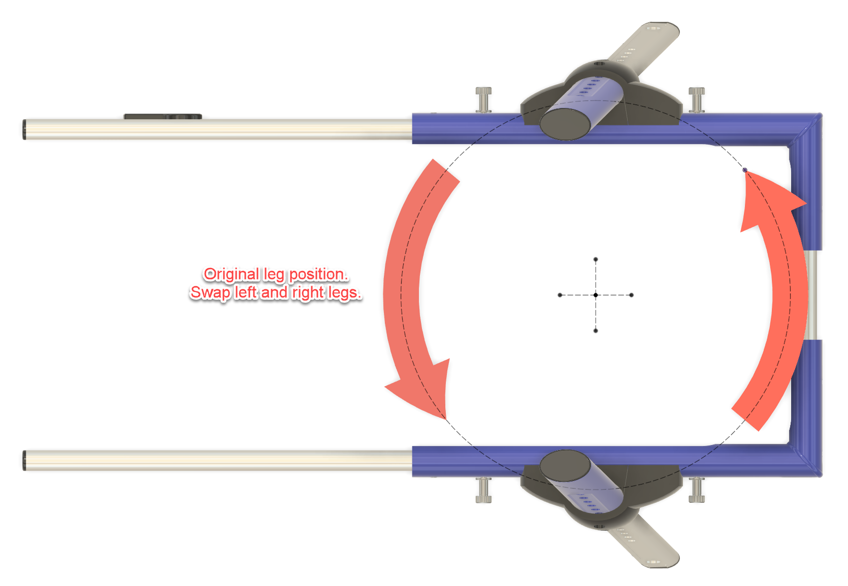
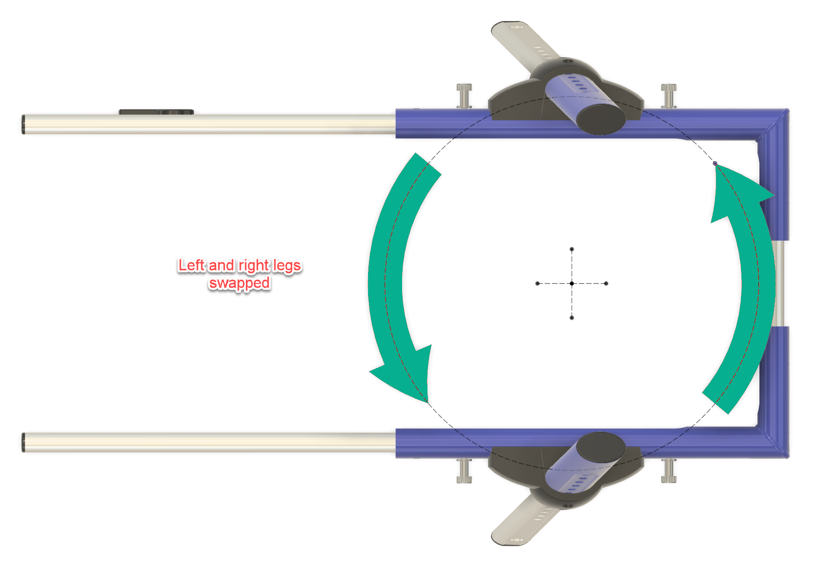
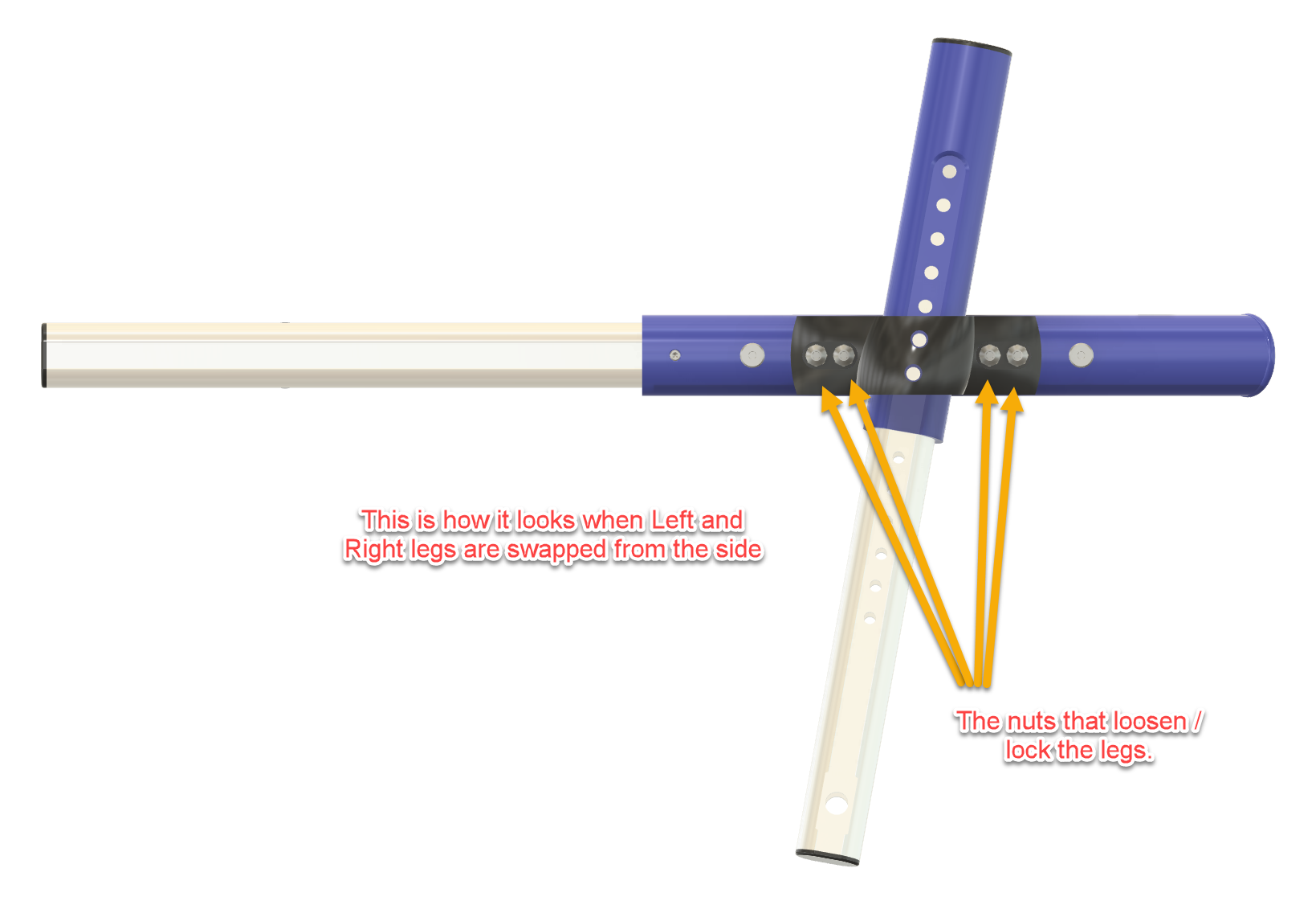
The left and right wheelchair legs are swapped, which changes the orientation of the wheel assemblies and provides the geometry needed for the trailing-arm suspension.

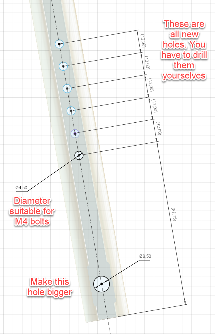
Additional 4.5 mm holes are drilled in the legs at 12 mm intervals. These provide several spring mounting positions so the suspension tension can be adjusted.

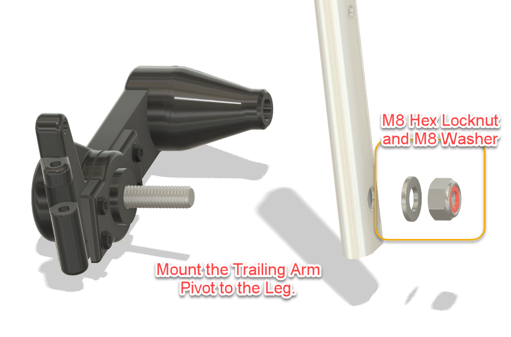
The lower existing hole is enlarged to 8.5 mm for mounting the trailing-arm pivot.

The original wheel components are retained where practical, while the newly designed parts form the suspension, bearing mounts and wheel guards.

3D printing the parts

All custom parts in my version were resin printed using Anycubic Water-Washable ABS-Like Resin V2.

To keep the wheelchair as light as possible, larger parts were printed hollow while retaining enough wall thickness and structural reinforcement for their intended load.

FDM printing should also be possible, but material choice and print orientation matter. These parts are structural: they carry the wheels, absorb shocks and experience repeated cyclic loading.

So this is not the ideal project for “three walls, 10% infill, she’ll be right.”

Strong and lightweight is the objective.

Jerry in his Modified Dog Wheelchair

Building it yourself

The project files include the printable components together with drawings and assembly illustrations showing how the conversion is made.

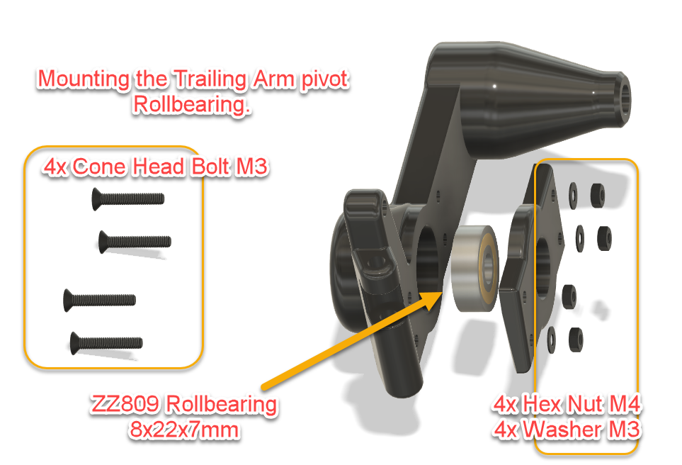
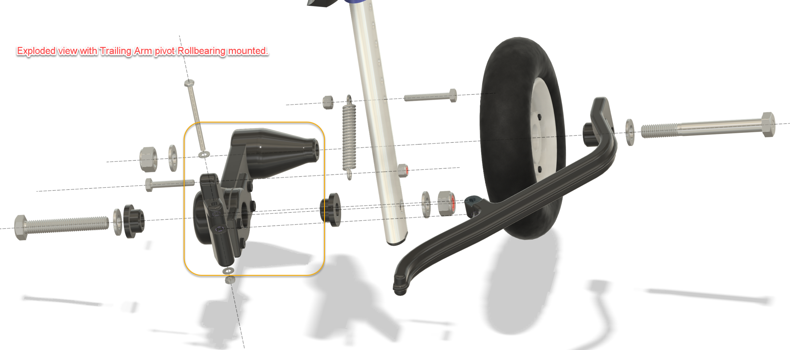
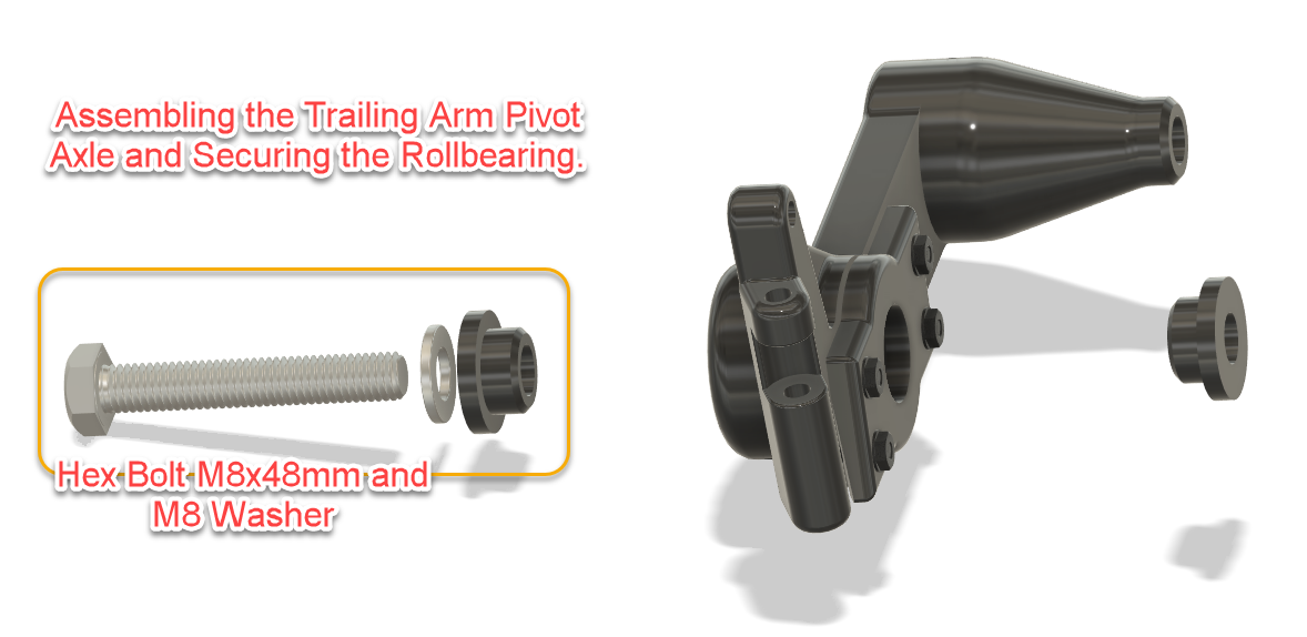
The build covers modification of the wheelchair legs, installation of the ball bearings, assembly of the trailing-arm pivots, spring mounting, wheel modification and final installation of the wheel guards.

Spring strength should be selected according to the dog’s weight. Each side of the suspension should be capable of supporting approximately half of the load carried by the rear of the wheelchair, with enough remaining travel for the suspension to actually do its job.

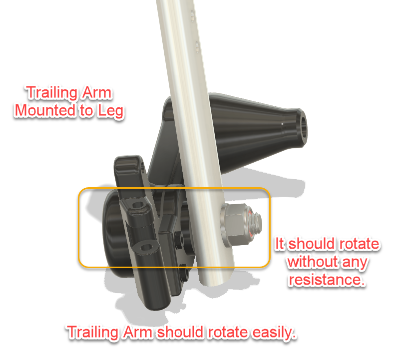
Once assembled, the trailing arms should rotate freely on their bearings without binding.

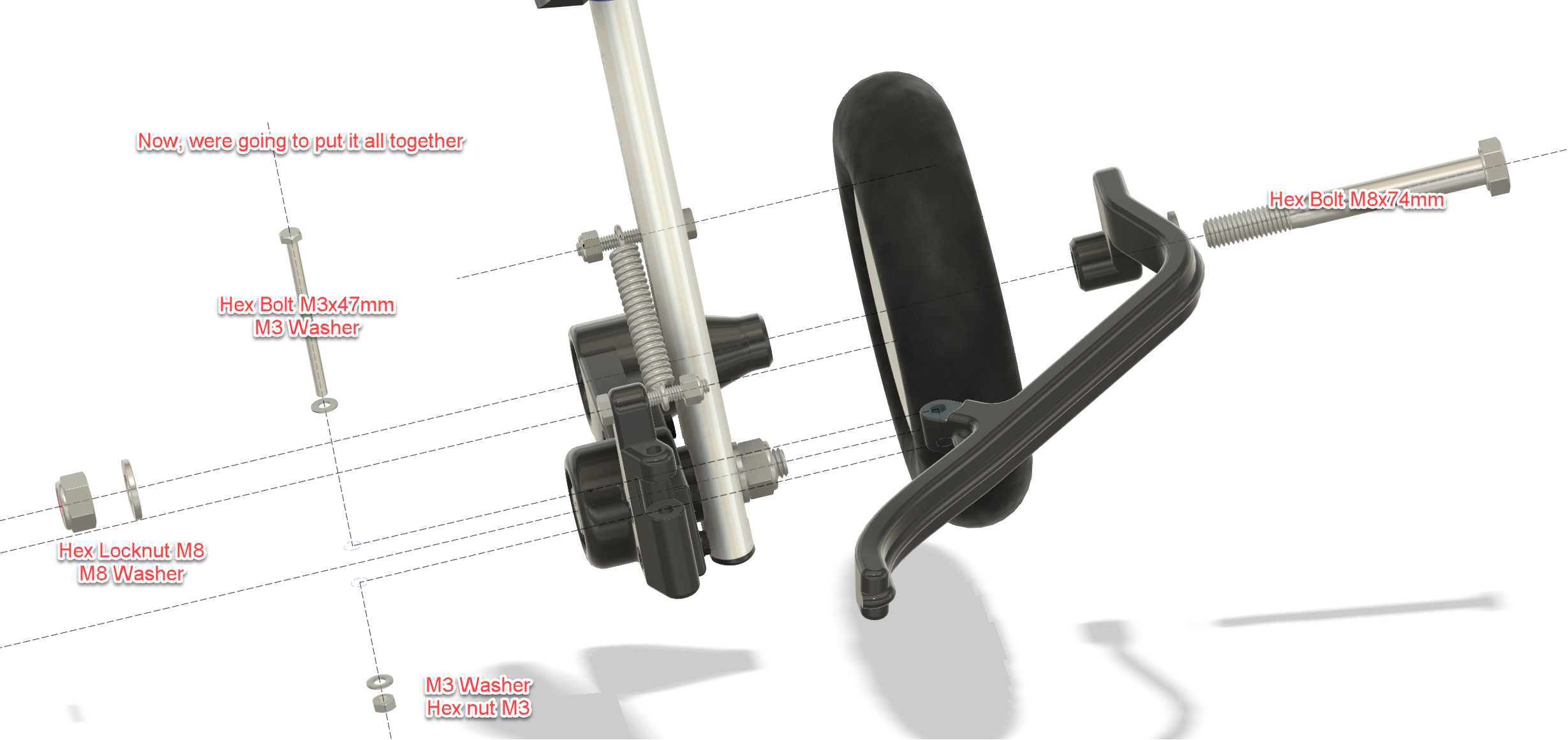
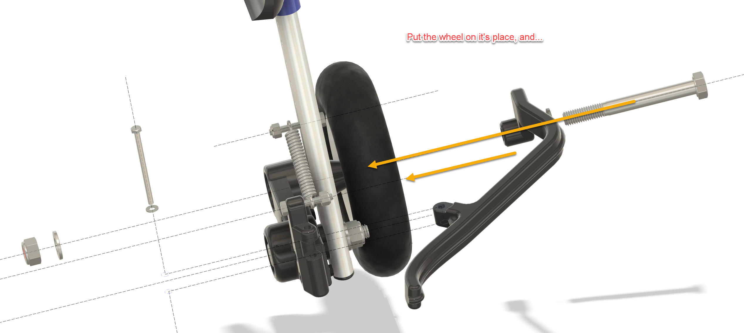
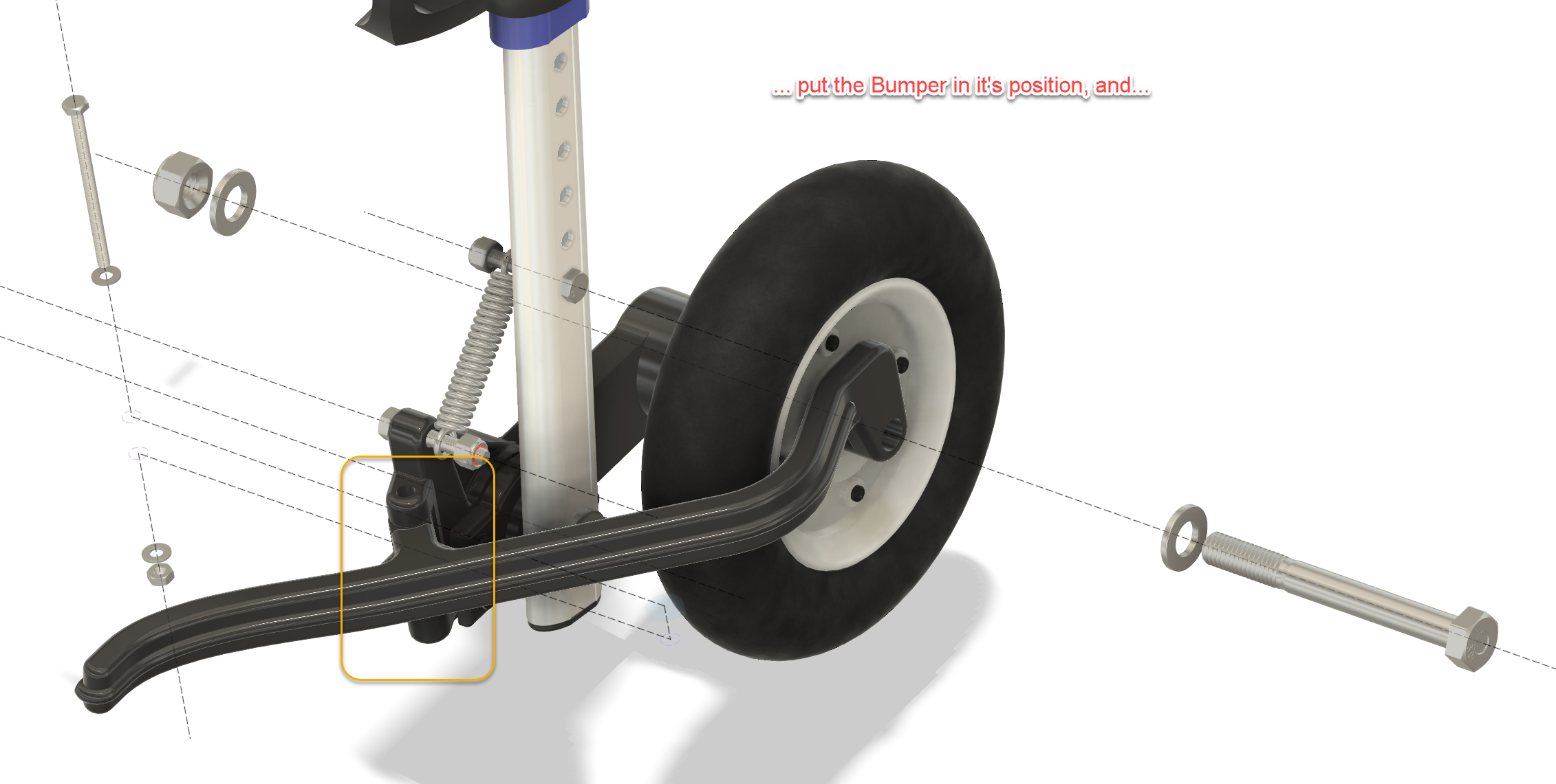
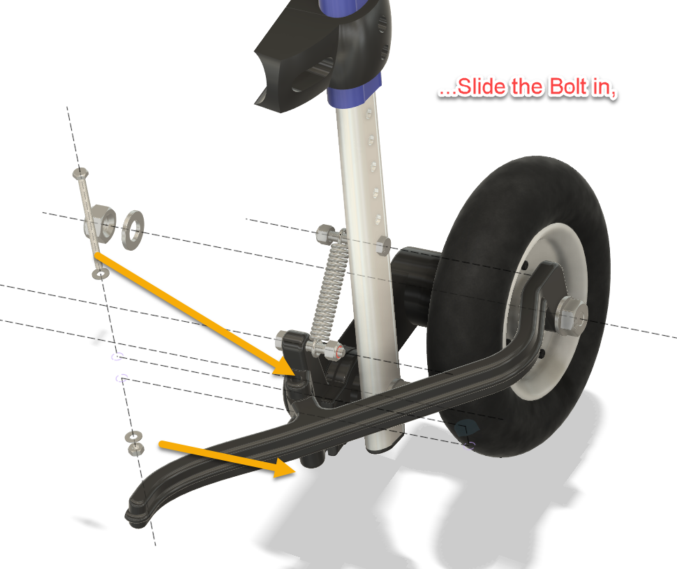
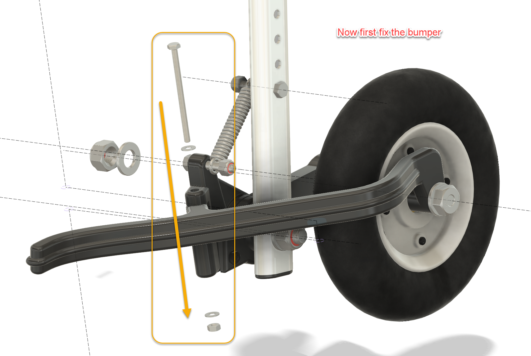
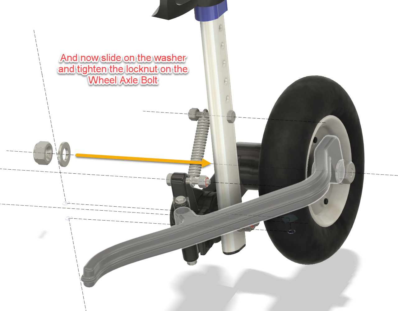
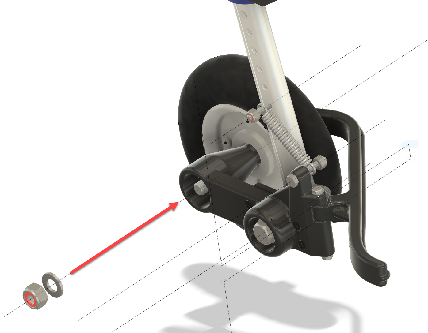
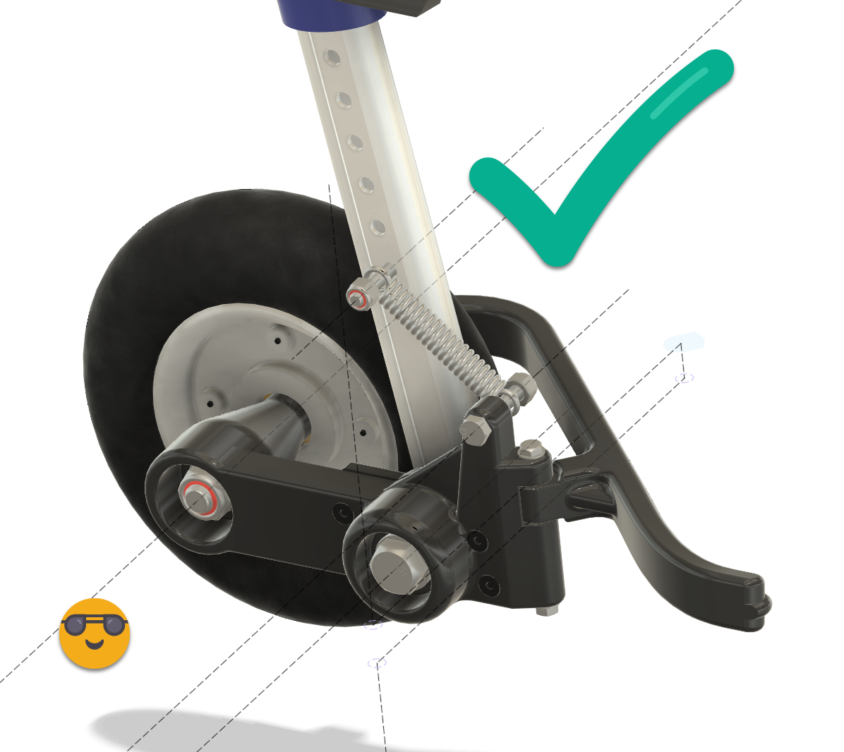
Please follow the assembling instructions in the pictures below.

The result

What started as an attempt to make the wheels turn a little easier ended up becoming a fairly substantial redesign of the rear wheel assembly.

Very much a case of:

“I’ll just improve this one small thing…”

Several CAD sessions, bearings, springs, bolts, prototypes and 3D prints later, the wheelchair had independent suspension.

But the important part is much simpler.

For our dachshund, it worked.

The wheels roll more freely, the suspension absorbs small shocks instead of transferring them directly into his back, and the guards prevent the wheels from catching abruptly on obstacles.

That made his walks easier and more comfortable — and gave him more opportunity to get outside and explore again.

And ultimately, that’s what this project was for.


Files included

The downloadable project contains the 3D-printable parts, a Bill of Materials for the required bearings, springs and fasteners, and illustrated assembly instructions showing the modifications and assembly sequence.

Feel free to adapt the design to your own situation. A button for downloading the original CAD file is added above. Dog wheelchairs, dogs and injuries differ, so consider this a starting point rather than a universal medical solution. Check the fit carefully, make sure nothing restricts or rubs against the dog, and adjust the suspension conservatively.
If you build one, I’d genuinely love to hear how it worked out.

Happy making — and, more importantly, happy walking.

Ready for some fun?

Does your dog hate rain?

→ The Dog TukTuk

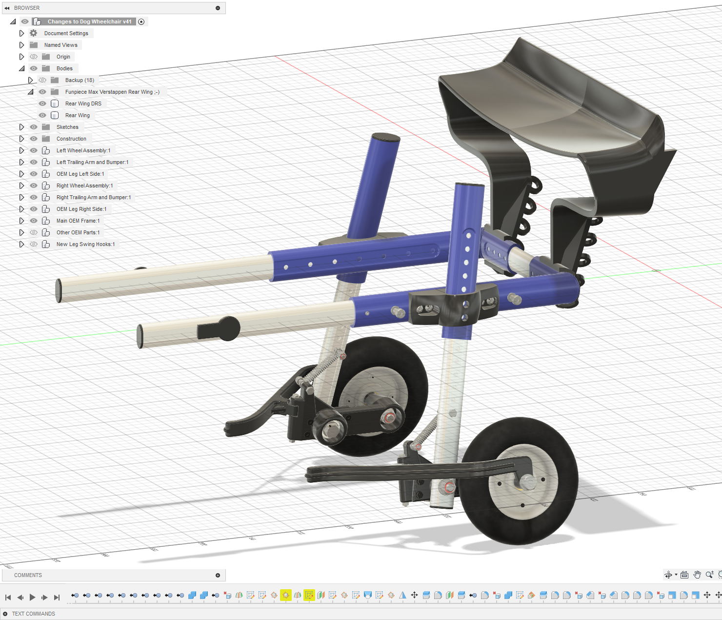
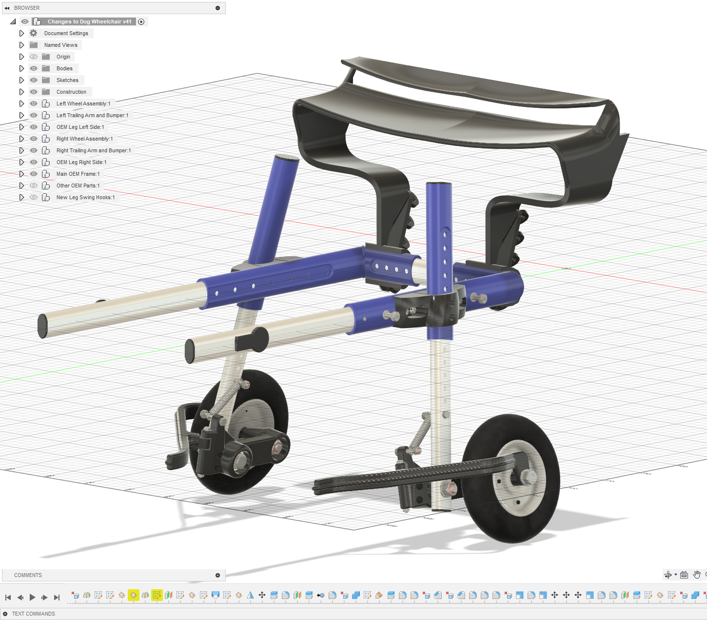
Why let a little rain ruin a perfectly good walk? Add a roof, a bit of aerodynamic styling and suddenly your dog has its own all-weather transport. The Dog TukTuk keeps the worst of the weather out while maintaining that essential “my human may have taken this project slightly too far” look.

  • Practical? Debatable.
  • Ridiculous? Absolutely.
  • Would I build it again? Obviously.

Is your dog extremely fast and in need of more downforce through the corners?

→ The Max Verstappen-worthy Rear Wing

When your dachshund starts suffering from high-speed oversteer, there is really only one sensible solution: more downforce.

Inspired by Formula 1, this completely unnecessary rear wing adds serious racing credentials to the wheelchair. And because ordinary downforce clearly wasn’t enough, there is even a DRS version for those crucial overtaking manoeuvres on the way to the food bowl.

  • Wind-tunnel tested? No.
  • FIA approved? Definitely not.
  • Does it make the wheelchair faster? Jerry thinks so.

| © 2026 | 9M² Creatory | Where imagination crystallizes |