Parallel-Jaw Precision Desktop Vise

Mechanically Synchronized Dual Lead-Screw Drive

This is a compact, high-strength 3D-printed desktop vise designed for model making, electronics, 3D printing and other precision work.

The main feature of this design is its mechanically synchronized dual lead-screw drive.

Instead of moving the jaw with a single lead screw, this vise uses two T8 lead screws, one on each side of the moving jaw. A single handwheel drives both lead screws simultaneously through a three-gear transmission.

Because both sides are mechanically linked, they always travel together. This prevents the moving jaw from twisting or skewing and keeps the jaws parallel throughout their entire range of motion, even when a workpiece is clamped off-centre.

The video demonstrates the mechanism in operation.

How it works

The centre gear is connected to the handwheel and drives the two outer gears simultaneously. These drive the two T8 lead screws at exactly the same rate.

Two 8 mm steel guide rods provide additional guidance and rigidity for the moving jaw.

The result is a very simple mechanical system:

one handwheel → three synchronized gears → two lead screws → one parallel-moving jaw

No belts, electronics or separate adjustments are required.

Designed for strength

Although most of the vise is 3D printed, the parts carrying the main mechanical loads are steel rods, T8 lead screws, bearings and conventional fasteners.

The design can therefore be made considerably stronger than its appearance might suggest.

How strong it becomes depends heavily on the material and print settings used. I printed the vise using FormFutura TitanX with three walls/perimeters.

For heavier use, I recommend increasing the number of walls/perimeters rather than relying primarily on a very high infill percentage.

Print orientation is also important. Structural parts should preferably be oriented so that the main clamping forces do not try to separate the printed layers.

Obviously, this is still a predominantly 3D-printed desktop vise — it isn’t intended to replace the 20 kg lump of cast iron bolted to your workbench. 🙂

Linear bearings

The moving jaw runs on two 8 mm guide rods.

Printable linear-bearing components are included with the model, so commercial linear bearings are not strictly required.

However, I found that standard 8 mm metal linear ball bearings provide better stability and smoother movement, so I recommend using them if possible.

Gear grip

The three gears transfer the force through the bearing assemblies.

If you experience slipping under higher clamping loads, thin rubber rings or O-rings can be placed between the gears and the outer races of the ball bearings to increase friction.

Additional hardware required

Besides the printed parts, you will need:

  • 3× deep-groove ball bearing — 15 × 32 × 9 mm
  • 2× T8 lead screw — 8 mm × 125 mm
  • 4× brass T8 trapezoidal lead-screw nut
  • 2× 8 mm steel guide rod — 172 mm
  • 2× 8 mm linear ball bearing — optional; printable alternatives are included
  • 2× M8 threaded rod/stud — 215 mm
  • 4× M8 nut
  • 2× M3 × 20 mm socket-head screw
  • 3× M3 × 15 mm socket-head screw
  • 10× M3 × 10 mm socket-head screw
  • 12× M4 × 30 mm socket-head screw
  • 2× M4 × 10 mm socket-head screw

Standard washers and/or small adjustment hardware visible in the assembly may also be required depending on tolerances and the exact hardware used.

Printing

My original vise was printed primarily on a Voron 2.4 using ABS filament

Some smaller parts were produced using the Anycubic Photon Mono X 6K resin printer using “ABS-like” resin.

The design does not depend on these particular printers. Any reasonably well-calibrated FDM printer capable of producing mechanically strong parts should be suitable.

STL Files

Applications

The vise was primarily designed for smaller precision work such as model building, electronics, PCB work, assembling 3D-printed parts and general maker projects.

The synchronized mechanism is particularly useful when working with parts that need to remain accurately aligned between the jaws.


Designed in Fusion 360 and built to answer a simple question:

How much of a proper precision desktop vise can you make with a 3D printer?

Quite a lot, apparently.

Thunderbirds

Growing up with Thunderbirds, these machines were impossible to forget. Decades later, I decided to recreate the four iconic rescue vehicles as 3D-printable models — not simply as display pieces, but as models designed from the start to be printed, assembled and enjoyed.

Existing models never quite matched what I was looking for, so I designed my own. Wherever practical, parts were separated by colour to minimize painting, while small details, alignment features and assembly tolerances were incorporated directly into the designs. The models combine FDM printing for the larger parts with resin printing where finer detail makes a real difference.


Thunderbird 1

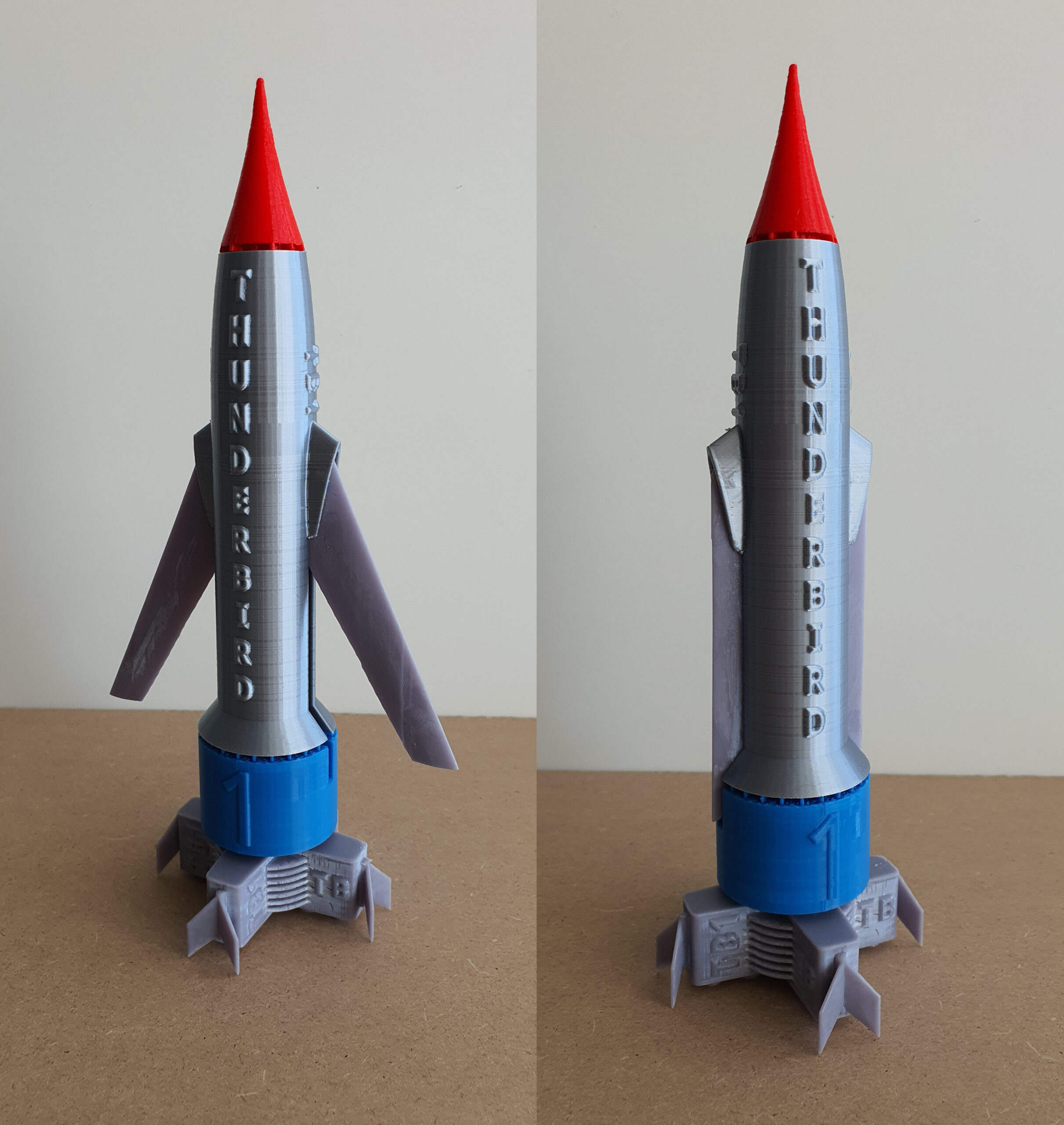
Thunderbird 1 looks deceptively simple: a sleek silver rocket with wings. That simplicity made getting its proportions and assembly right particularly important. I wanted a model that captured the unmistakable silhouette of the original while remaining straightforward to print and put together. The wings can fold and unfold

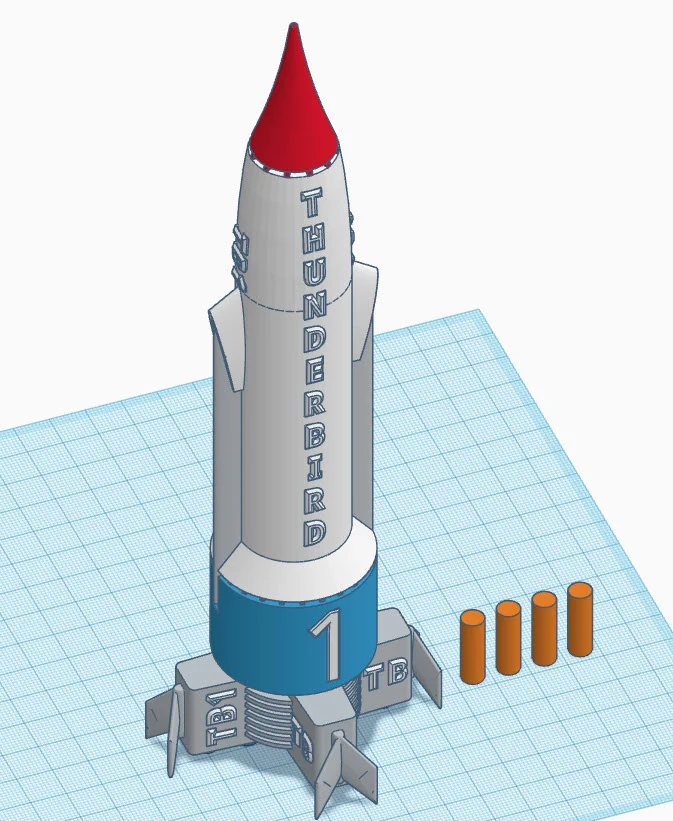
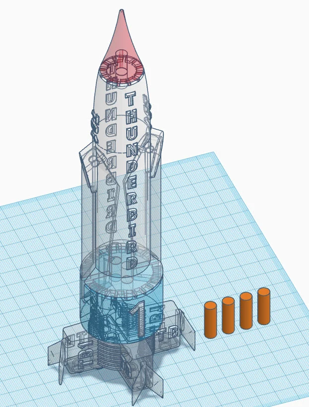
The model is divided into colour-separated parts, with alignment dowels making assembly precise and repeatable. Parts that slide into or over one another have approximately 0.2 mm clearance, which should provide a good fit on a reasonably calibrated printer.

The main body can be printed without supports except for the wings and rocket engine. I printed the smaller detailed parts in SLA resin and the larger components in FDM.

And because one Thunderbird apparently wasn’t enough, this was only the beginning.


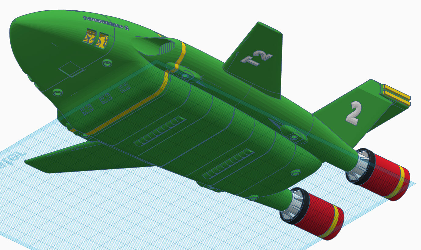
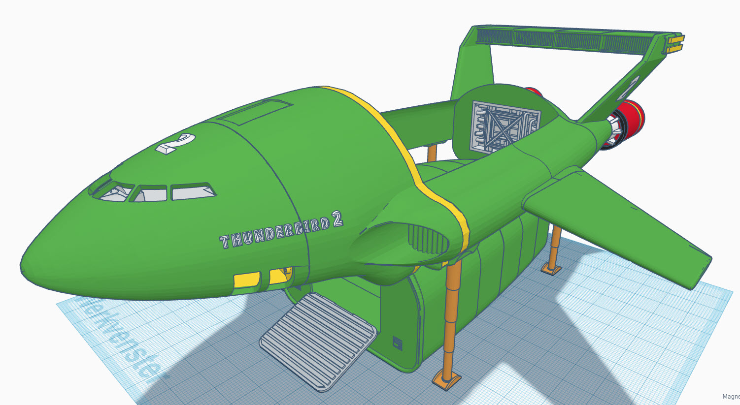
Thunderbird 2

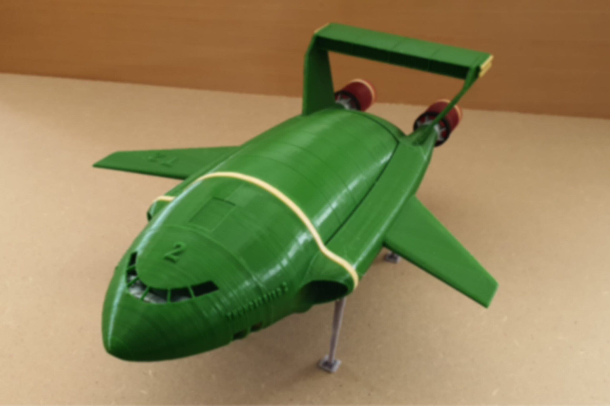
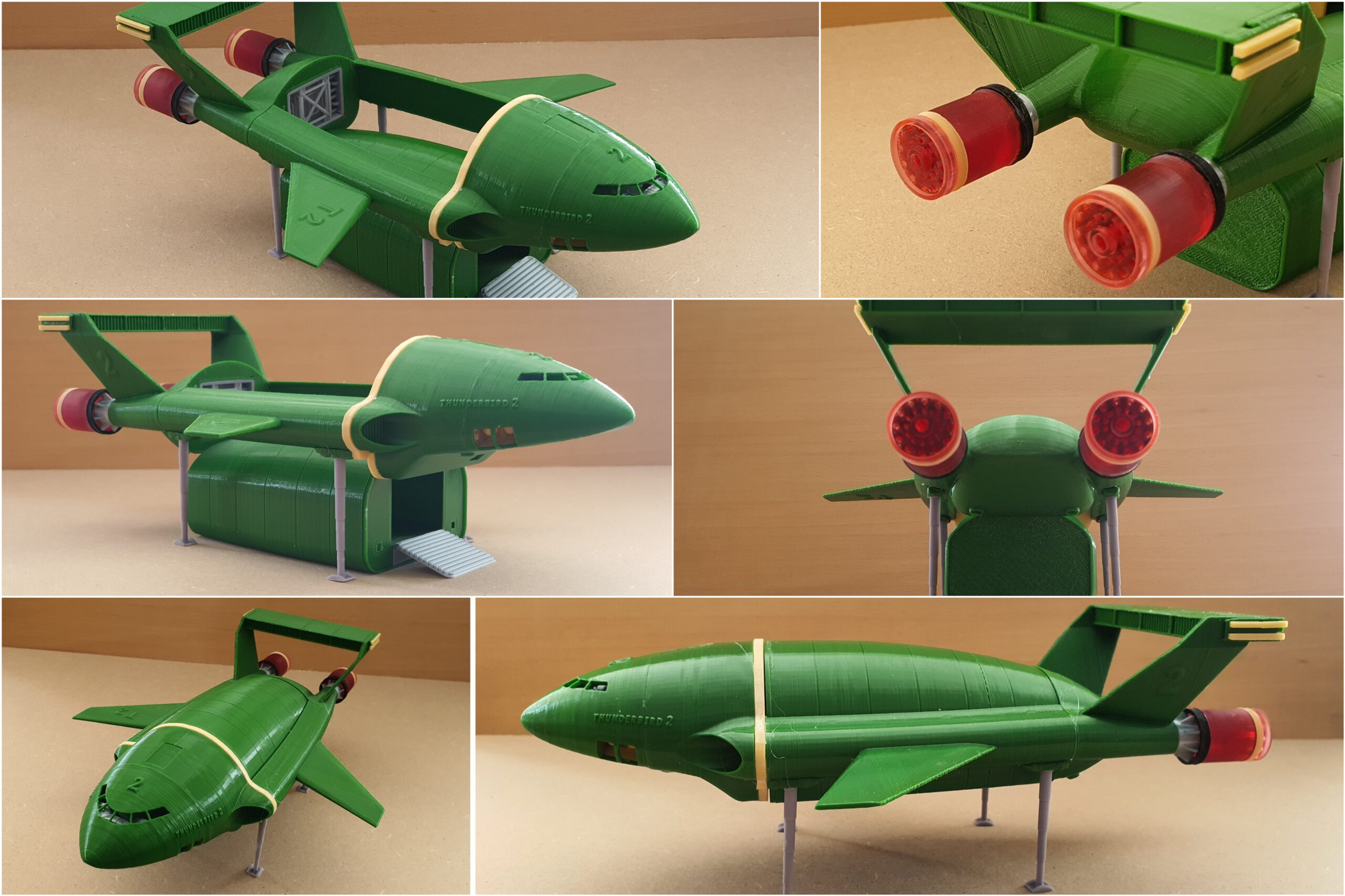
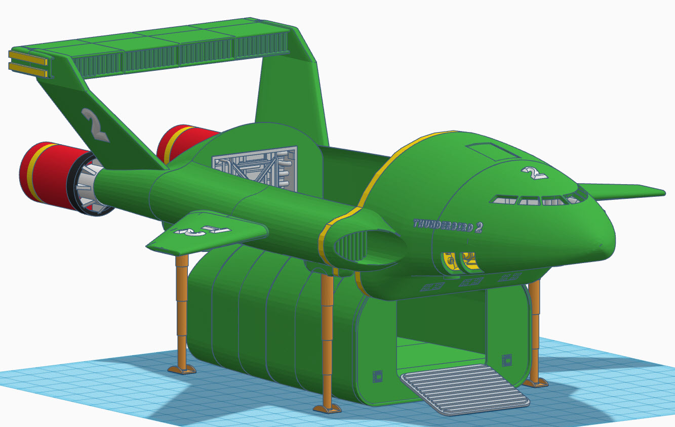
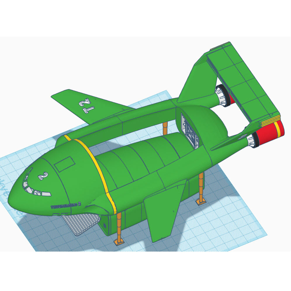
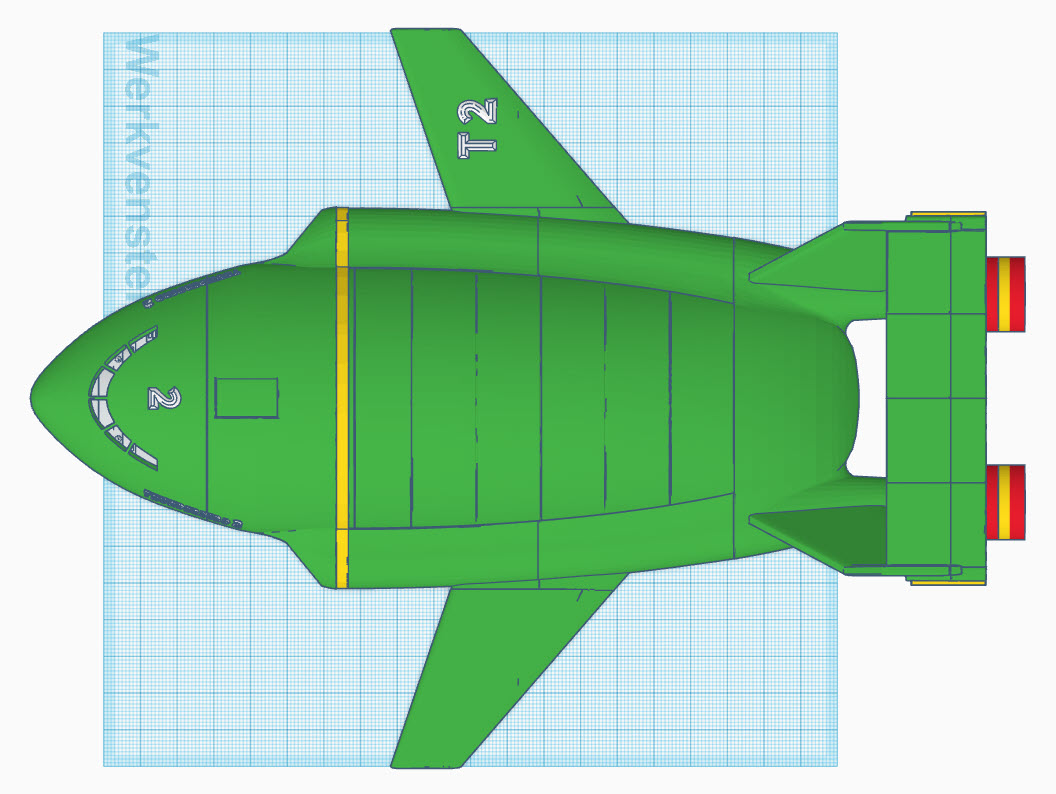
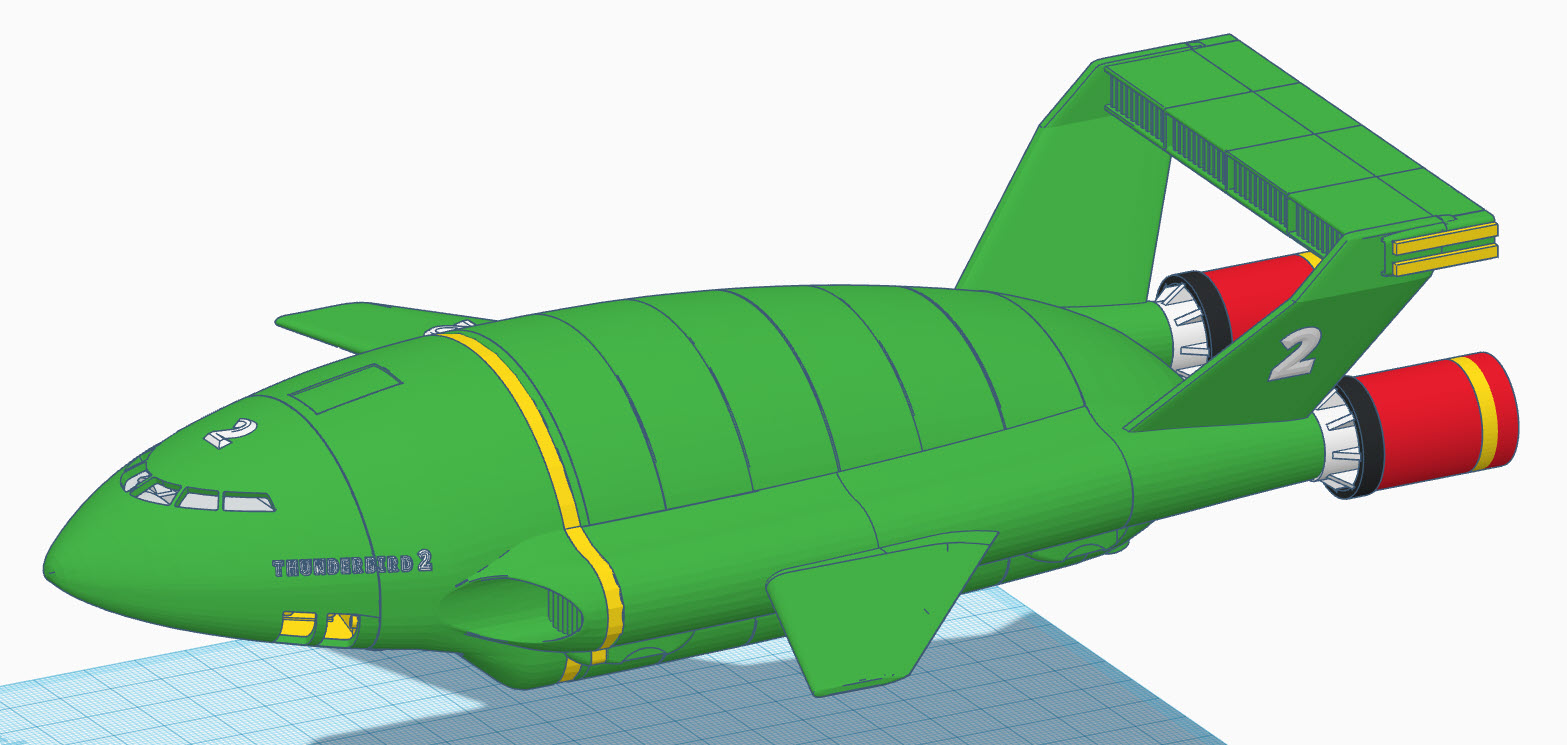
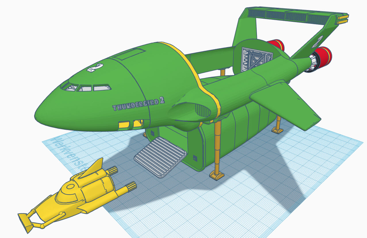
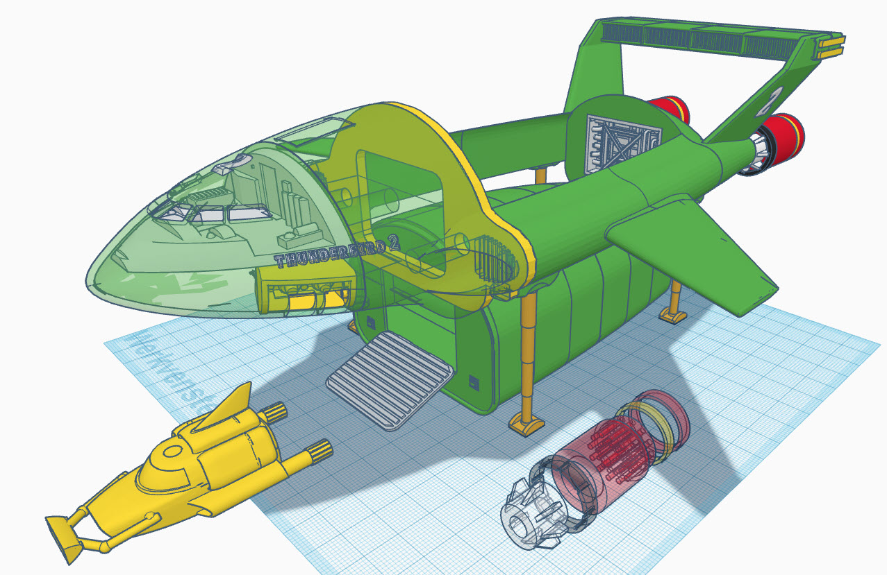
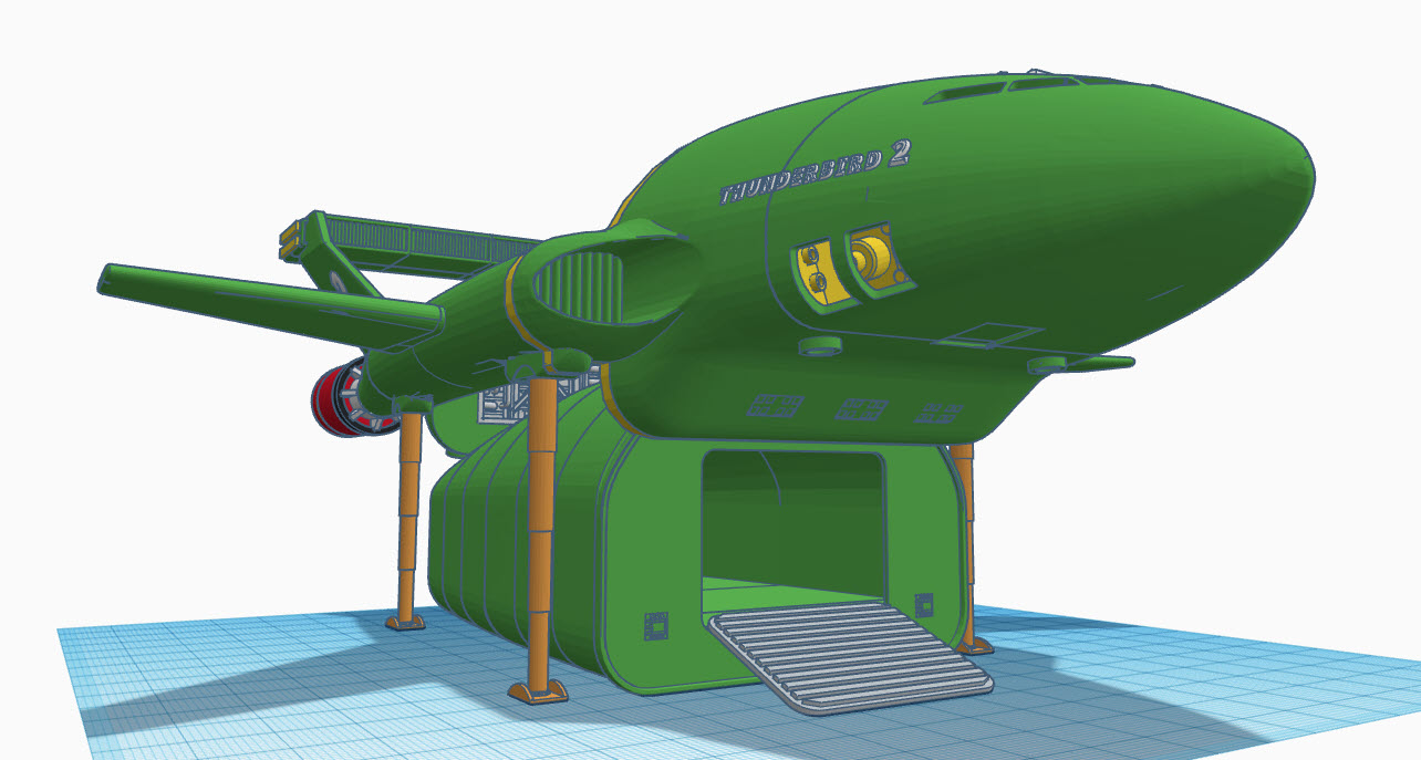
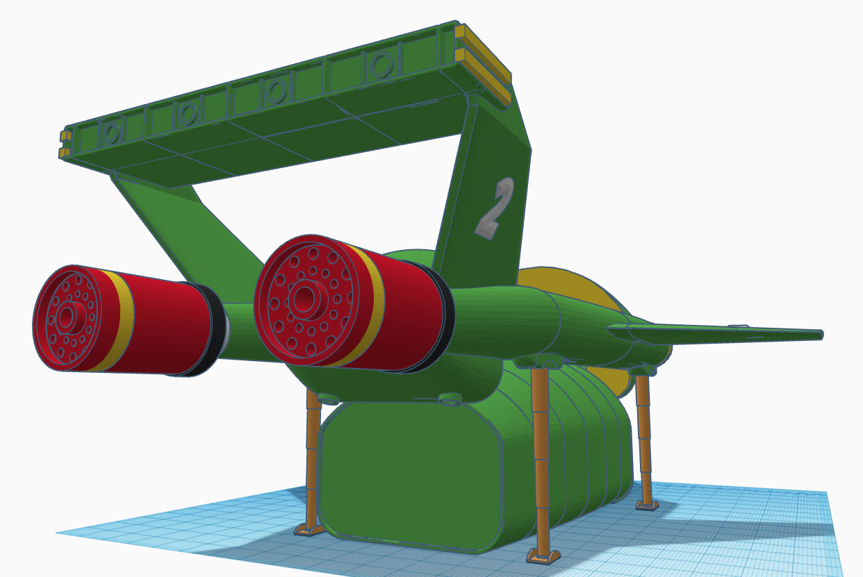
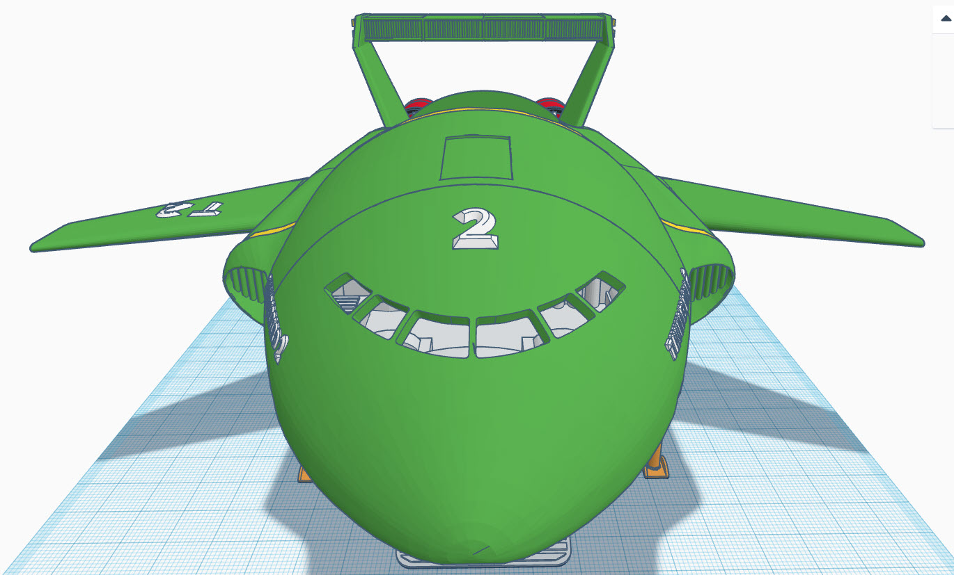
Of all the Thunderbirds, Thunderbird 2 is probably the one that presented the most interesting design challenges. Its huge flowing fuselage, the landing gear, removable pod and small external details make it much more than just a green shell with wings.

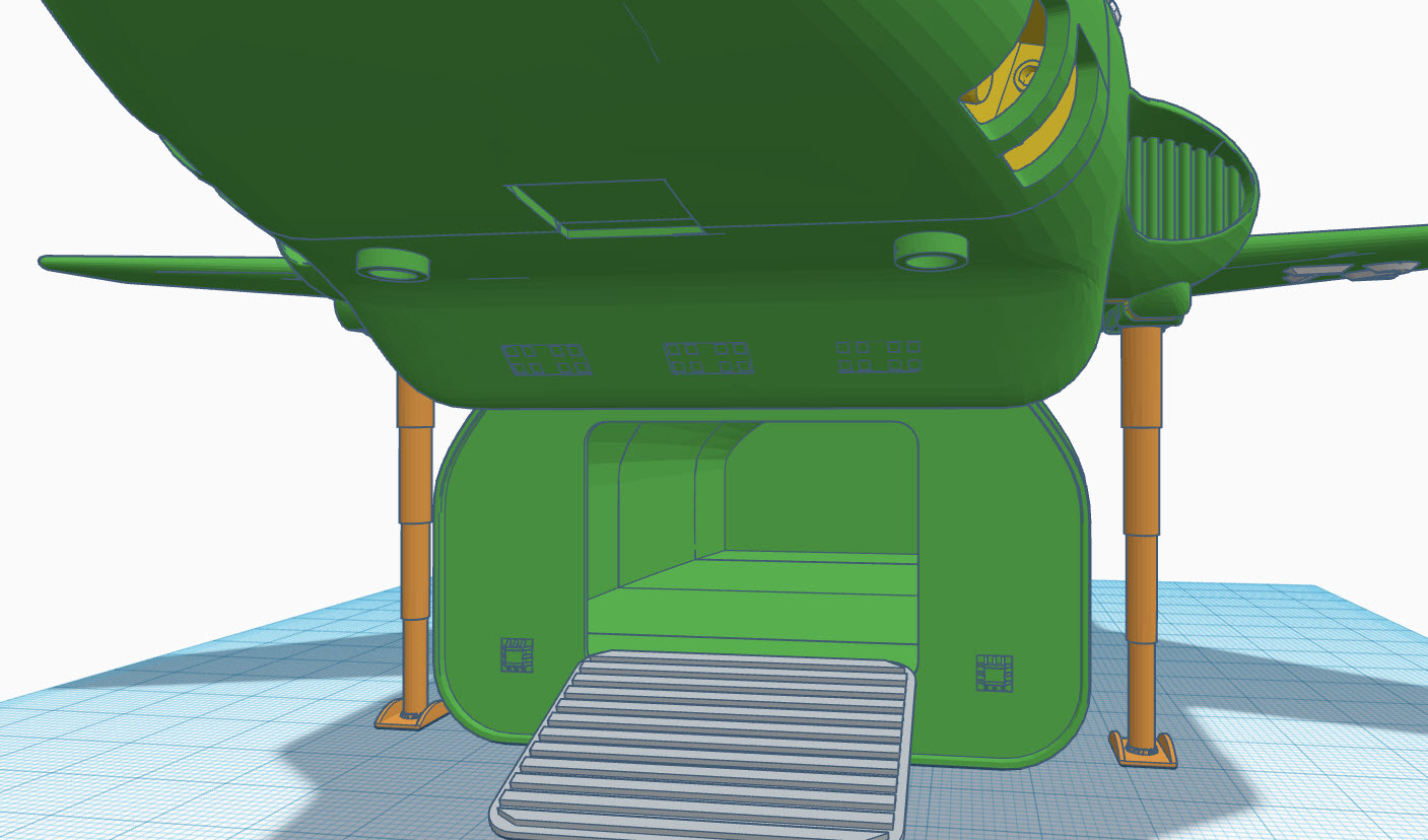
The landing gear cannot retract into the model. Because the mechanism is too delicate at this scale, but the legs can be removed if the model is mainly intended for display with the pod inserted. The tail and stabilizer sections are separate parts that slide into position, while small details such as lettering are designed so they can be printed separately in the appropriate colours.

Naturally, Thunderbird 2 wouldn’t be complete without a pod. I included one with the model — and even added a small one-piece Thunderbird 4 to live inside it.


Thunderbird 3

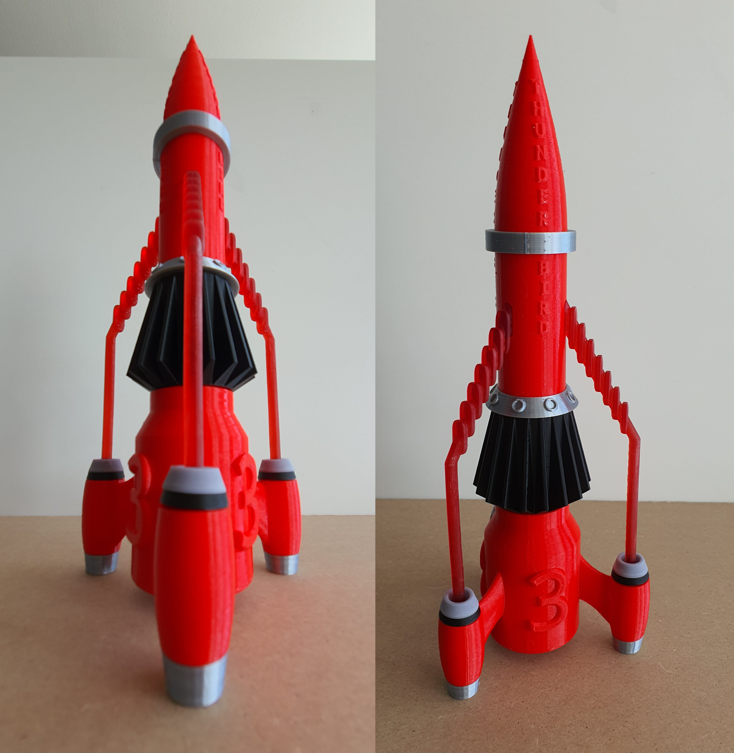
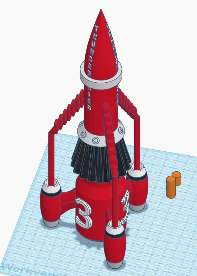
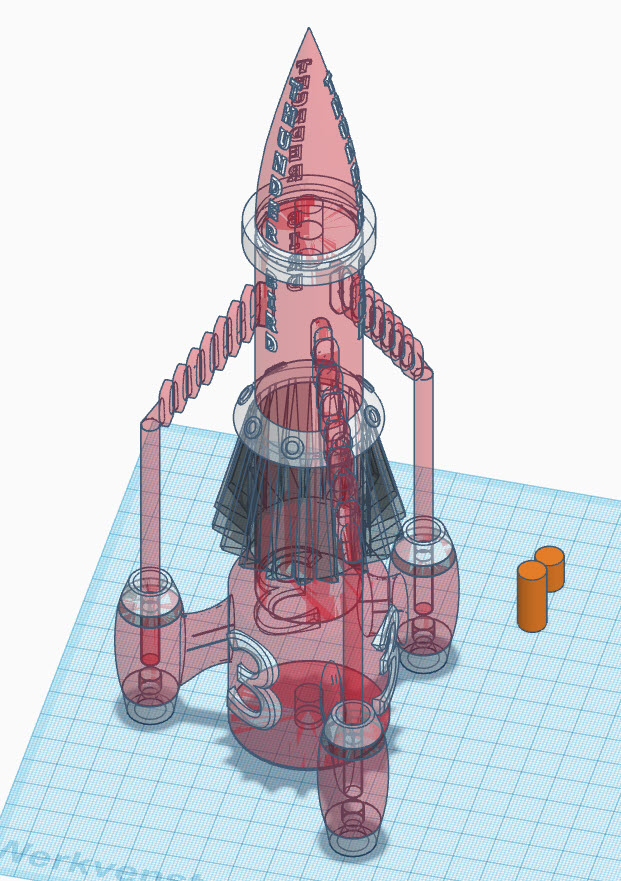
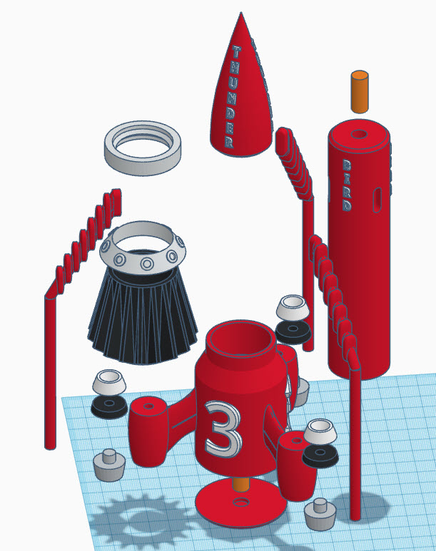
Thunderbird 3 is essentially a collection of long cylinders, fins and rocket engines — which sounds easy until you try to turn that distinctive shape into something that prints cleanly and assembles accurately.

I split the model into colour-separated sections so that very little painting is required. Alignment dowels help keep the tall structure straight during assembly, while the individual components use roughly 0.2 mm clearance where they fit together.

Almost everything can be printed without supports; the jet arms are the main exception. As with the other models, I used SLA resin for the smaller detailed components and FDM for the larger structural parts.

The result is a model that looks suitably ready to leave Tracy Island vertically and in a great hurry.

STL Files TB3

I used an SLA printer for small detailed parts, and a FDM printer for the rest.

Thunderbird 4

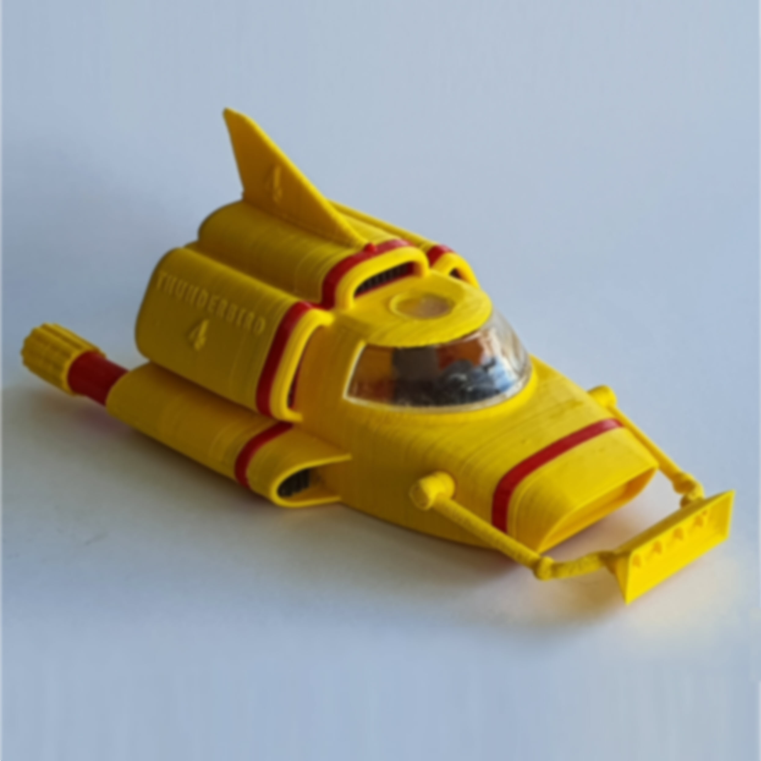
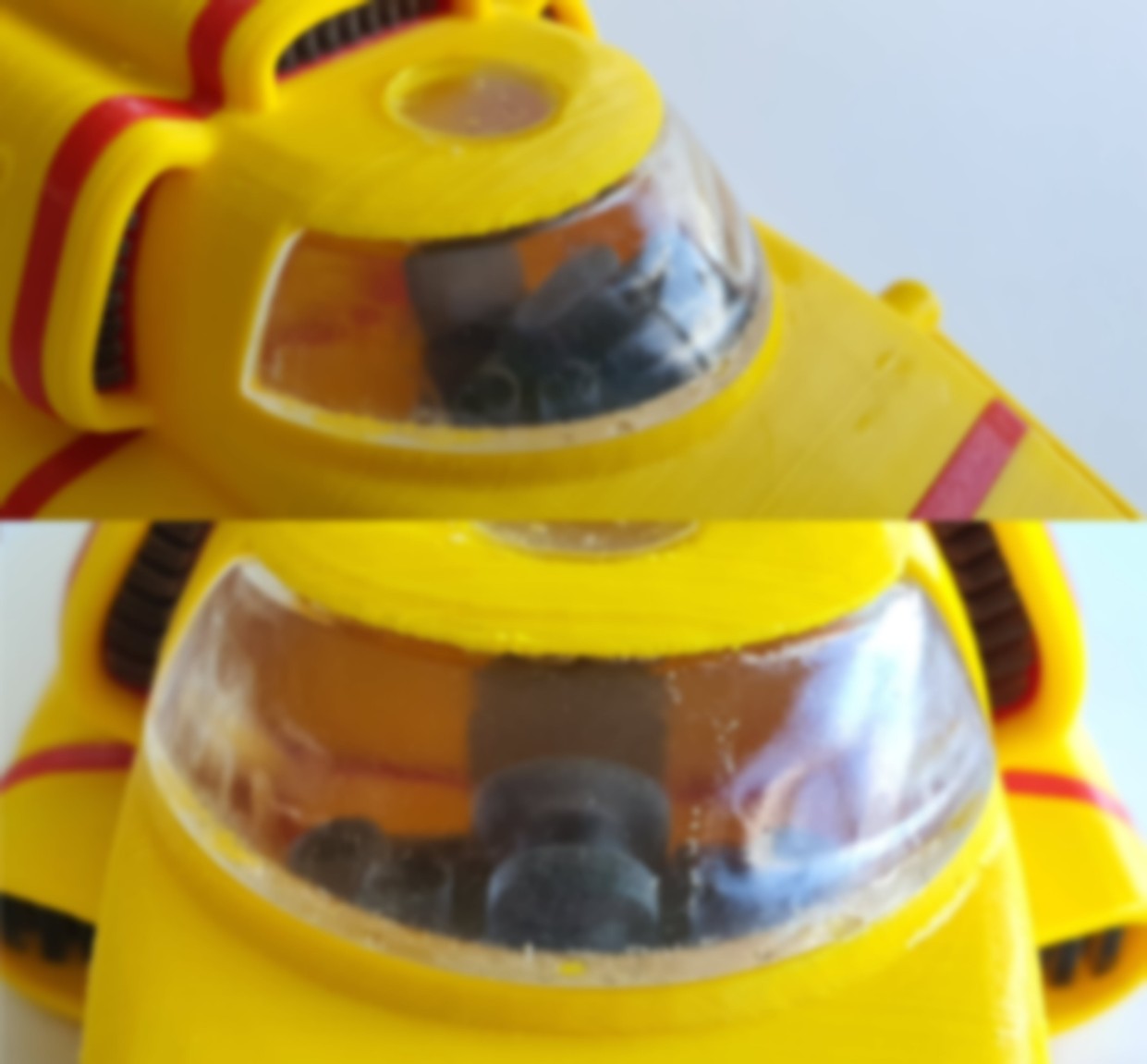
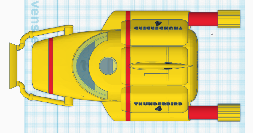
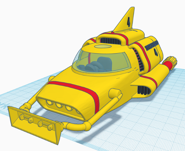
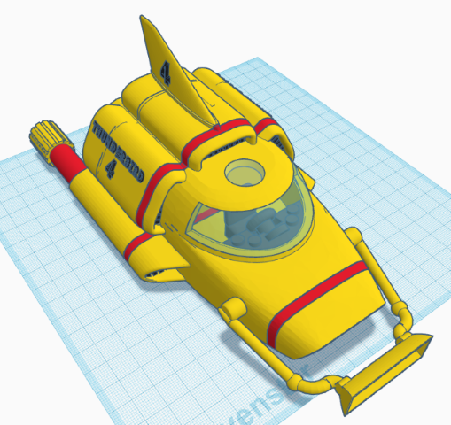
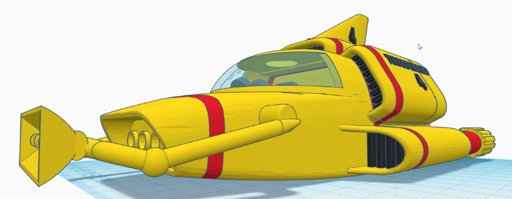
Smallest of the original Thunderbird machines, but for this model I deliberately gave Thunderbird 4 a larger scale of its own. That allowed me to preserve far more of the characteristic shapes and details of the little yellow submersible than would have been possible if it had been scaled to fit inside Thunderbird 2.

As with the other models, it is divided into separate colour parts wherever practical, minimizing the need for painting. Alignment dowels help position the components accurately during assembly, while the combination of FDM and resin printing makes it possible to retain the finer details without unnecessarily complicating the larger parts.

Thunderbird 2 does include its own miniature Thunderbird 4, but that is a separate, simplified one-piece model designed specifically to fit inside the pod. The model presented here is the full, larger and much more detailed version.

Small rescue craft, considerably less small 3D print.

Printing & Assembly

The models were designed with 3D printing in mind. Almost all parts can be printed without supports when oriented correctly. In some cases this means printing a part upright rather than in what might seem the most obvious position. A few parts inevitably require supports because of their geometry.
Tall or narrow parts printed upright can be more vulnerable to being knocked loose by the nozzle. If that becomes a problem, there are several ways to improve reliability:

  • Use a small amount of adhesive on the print bed to improve adhesion.
  • Enable Z-hop on retraction, so the nozzle lifts slightly while travelling over the print.
  • Add a raft to give tall or narrow parts a more stable base.

Parts that slide into or over each other were designed with approximately 0.2 mm clearance. This should provide a good fit on a properly calibrated printer, although minor sanding or adjustment may occasionally be required.

I printed the small, highly detailed parts on an SLA resin printer, as many FDM printers may struggle to reproduce the finer details cleanly. The larger structural parts were printed using FDM.
The STL filenames include both the intended colour and the number of copies required, making it easier to prepare the complete set of parts before assembly.
As always with 3D printing, printer calibration, material choice and slicer settings can make a difference — so consider the tolerances and print orientations a starting point rather than a law of nature.
STL Files TB4


| © 2026 | 9M² Creatory | Where imagination crystallizes |