My name is Tom, and I have always been driven by a simple question: *What if I built it myself?*
From a compact 9-square-meter workshop, I design, prototype and create a wide variety of projects ranging from 3D printing, CNC machining and laser engraving to electronics, woodworking, metalworking and home automation. I particularly enjoy combining different materials and manufacturing techniques, bringing together wood, metal, plastics and electronics into functional and often unique creations.
Professionally, I have spent decades in technology and cybersecurity. Personally, I remain fascinated by engineering, craftsmanship, astronomy, and the endless possibilities that emerge when curiosity meets creativity.
What starts as a sketch, an observation, or a random idea often evolves into a tangible object, a working prototype, or a practical solution. This site is a collection of projects, ideas, discoveries, and inspirations. Some are finished, some are still evolving, and some may never leave the drawing board. Together they represent an ongoing journey of exploration, learning, and making.
Welcome to my 9M² Creatory — where imagination crystallizes.
This is a compact, high-strength 3D-printed desktop vise designed for model making, electronics, 3D printing and other precision work.
The main feature of this design is its mechanically synchronized dual lead-screw drive.
Desktop Vise
Desktop Vise
Desktop Vise
Desktop Vise
Desktop Vise
Instead of moving the jaw with a single lead screw, this vise uses two T8 lead screws, one on each side of the moving jaw. A single handwheel drives both lead screws simultaneously through a three-gear transmission.
Because both sides are mechanically linked, they always travel together. This prevents the moving jaw from twisting or skewing and keeps the jaws parallel throughout their entire range of motion, even when a workpiece is clamped off-centre.
The video demonstrates the mechanism in operation.
How it works
The centre gear is connected to the handwheel and drives the two outer gears simultaneously. These drive the two T8 lead screws at exactly the same rate.
Two 8 mm steel guide rods provide additional guidance and rigidity for the moving jaw.
The result is a very simple mechanical system:
one handwheel → three synchronized gears → two lead screws → one parallel-moving jaw
No belts, electronics or separate adjustments are required.
Designed for strength
Although most of the vise is 3D printed, the parts carrying the main mechanical loads are steel rods, T8 lead screws, bearings and conventional fasteners.
The design can therefore be made considerably stronger than its appearance might suggest.
How strong it becomes depends heavily on the material and print settings used. I printed the vise using FormFutura TitanX with three walls/perimeters.
For heavier use, I recommend increasing the number of walls/perimeters rather than relying primarily on a very high infill percentage.
Print orientation is also important. Structural parts should preferably be oriented so that the main clamping forces do not try to separate the printed layers.
Obviously, this is still a predominantly 3D-printed desktop vise — it isn’t intended to replace the 20 kg lump of cast iron bolted to your workbench. 🙂
No Caption
No Caption
No Caption
No Caption
No Caption
No Caption
Linear bearings
The moving jaw runs on two 8 mm guide rods.
Printable linear-bearing components are included with the model, so commercial linear bearings are not strictly required.
However, I found that standard 8 mm metal linear ball bearings provide better stability and smoother movement, so I recommend using them if possible.
Gear grip
The three gears transfer the force through the bearing assemblies.
If you experience slipping under higher clamping loads, thin rubber rings or O-rings can be placed between the gears and the outer races of the ball bearings to increase friction.
Additional hardware required
Besides the printed parts, you will need:
3× deep-groove ball bearing — 15 × 32 × 9 mm
2× T8 lead screw — 8 mm × 125 mm
4× brass T8 trapezoidal lead-screw nut
2× 8 mm steel guide rod — 172 mm
2× 8 mm linear ball bearing — optional; printable alternatives are included
2× M8 threaded rod/stud — 215 mm
4× M8 nut
2× M3 × 20 mm socket-head screw
3× M3 × 15 mm socket-head screw
10× M3 × 10 mm socket-head screw
12× M4 × 30 mm socket-head screw
2× M4 × 10 mm socket-head screw
Standard washers and/or small adjustment hardware visible in the assembly may also be required depending on tolerances and the exact hardware used.
Printing
My original vise was printed primarily on a Voron 2.4 using ABS filament
Some smaller parts were produced using the Anycubic Photon Mono X 6K resin printer using “ABS-like” resin.
The design does not depend on these particular printers. Any reasonably well-calibrated FDM printer capable of producing mechanically strong parts should be suitable.
The vise was primarily designed for smaller precision work such as model building, electronics, PCB work, assembling 3D-printed parts and general maker projects.
The synchronized mechanism is particularly useful when working with parts that need to remain accurately aligned between the jaws.
Designed in Fusion 360 and built to answer a simple question:
How much of a proper precision desktop vise can you make with a 3D printer?
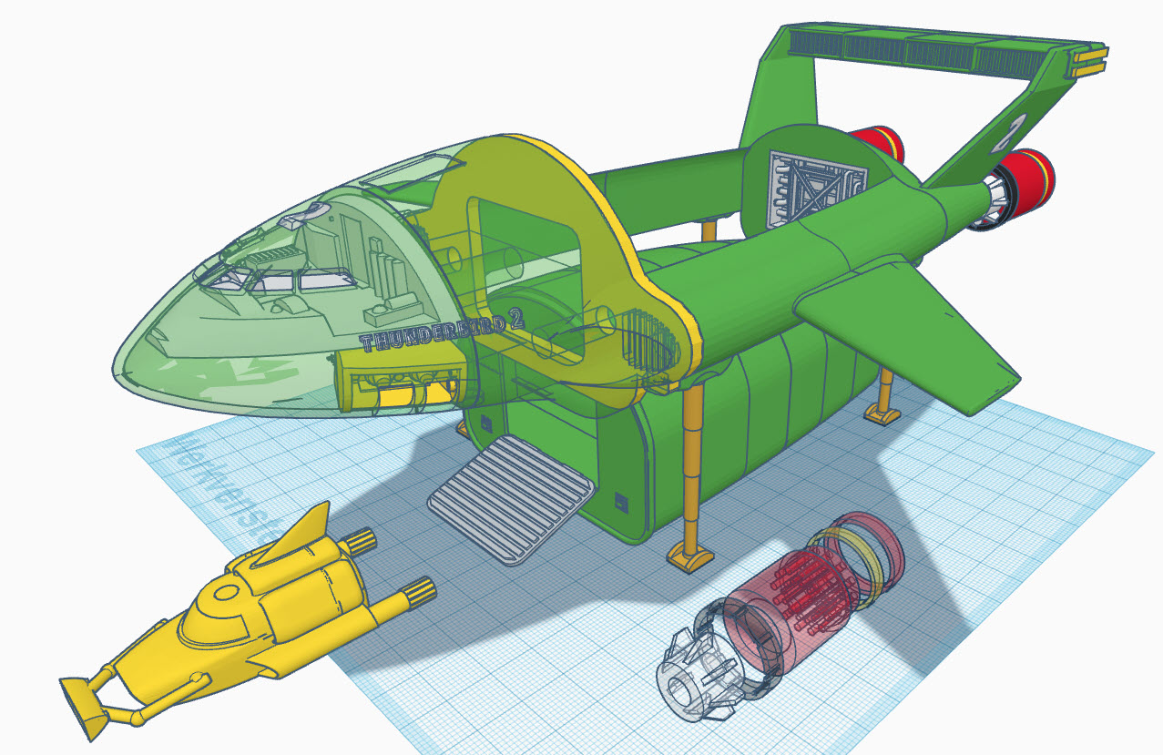
Growing up with Thunderbirds, these machines were impossible to forget. Decades later, I decided to recreate the four iconic rescue vehicles as 3D-printable models — not simply as display pieces, but as models designed from the start to be printed, assembled and enjoyed.
Existing models never quite matched what I was looking for, so I designed my own. Wherever practical, parts were separated by colour to minimize painting, while small details, alignment features and assembly tolerances were incorporated directly into the designs. The models combine FDM printing for the larger parts with resin printing where finer detail makes a real difference.
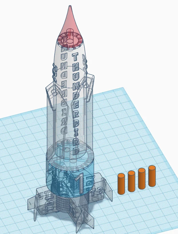
Thunderbird 1
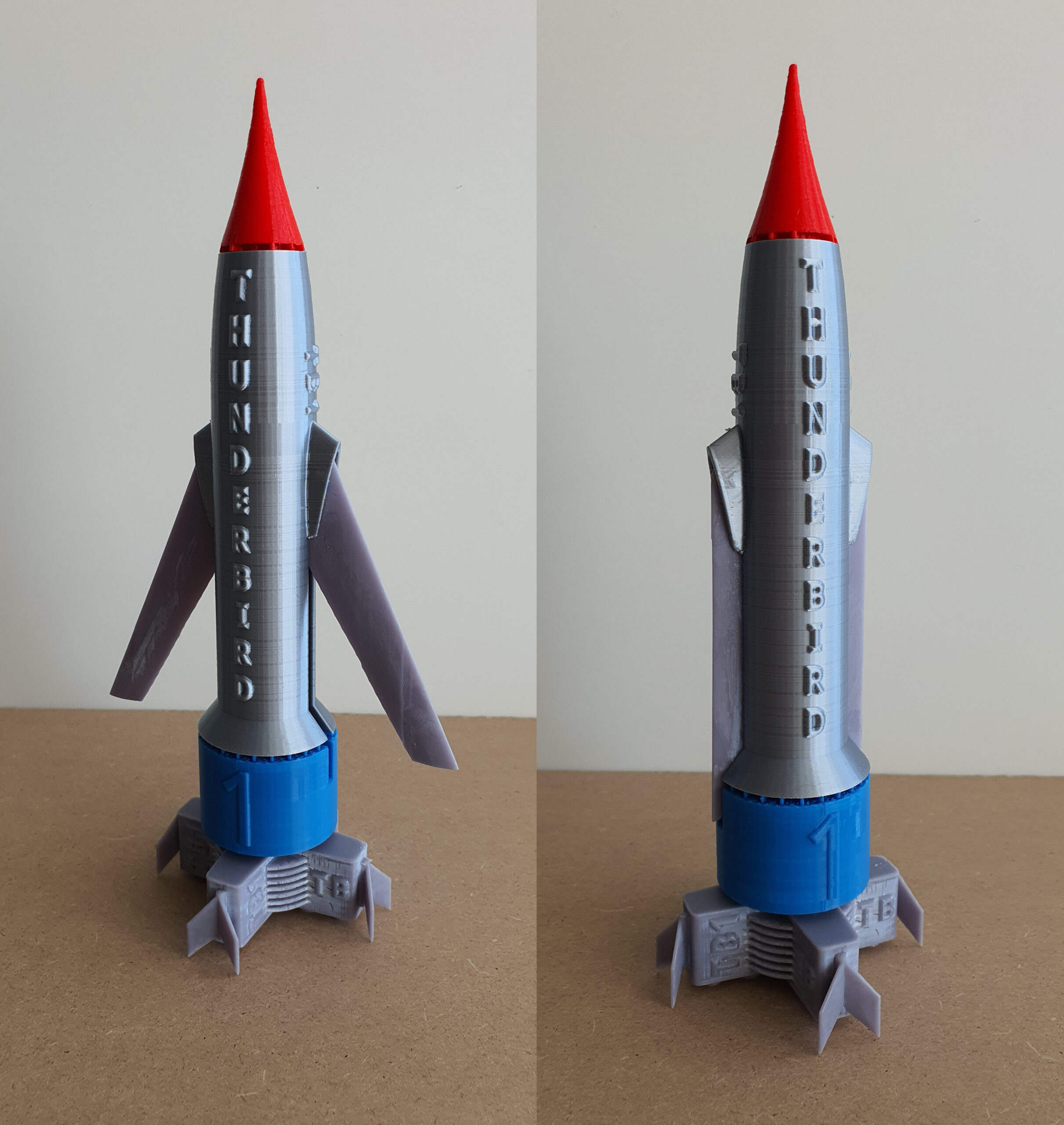
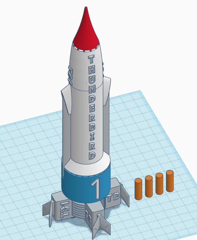
Thunderbird 1 looks deceptively simple: a sleek silver rocket with wings. That simplicity made getting its proportions and assembly right particularly important. I wanted a model that captured the unmistakable silhouette of the original while remaining straightforward to print and put together. The wings can fold and unfold
Thunderbird 1
Thunderbird 1
The model is divided into colour-separated parts, with alignment dowels making assembly precise and repeatable. Parts that slide into or over one another have approximately 0.2 mm clearance, which should provide a good fit on a reasonably calibrated printer.
The main body can be printed without supports except for the wings and rocket engine. I printed the smaller detailed parts in SLA resin and the larger components in FDM.
And because one Thunderbird apparently wasn’t enough, this was only the beginning.
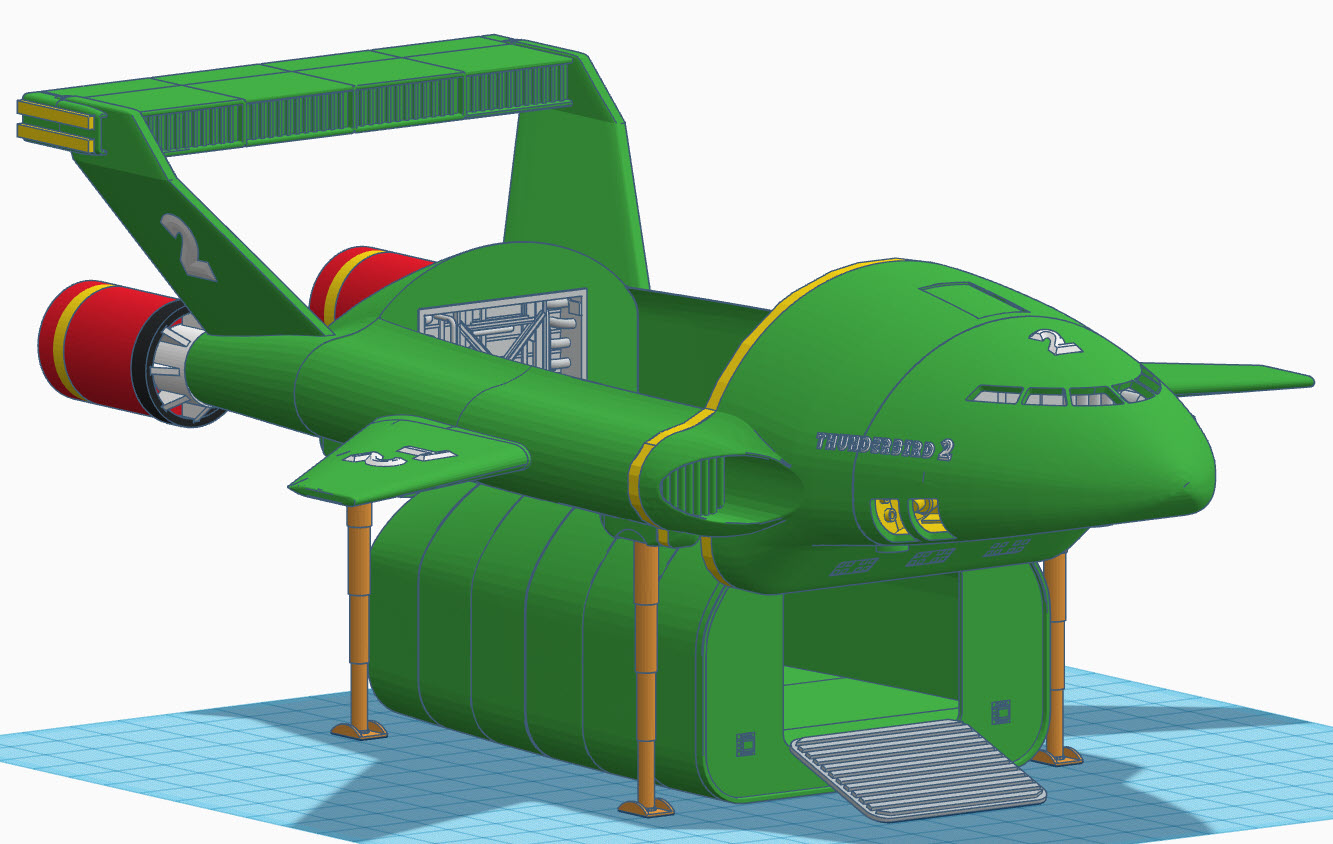
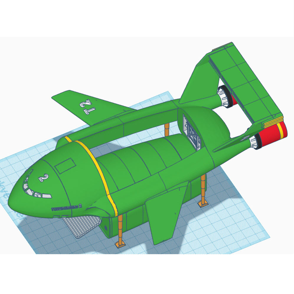
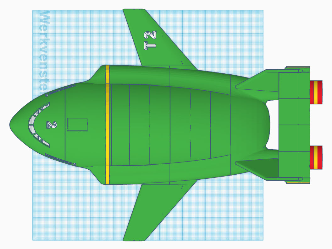
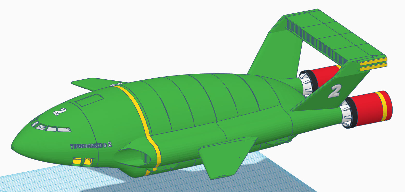
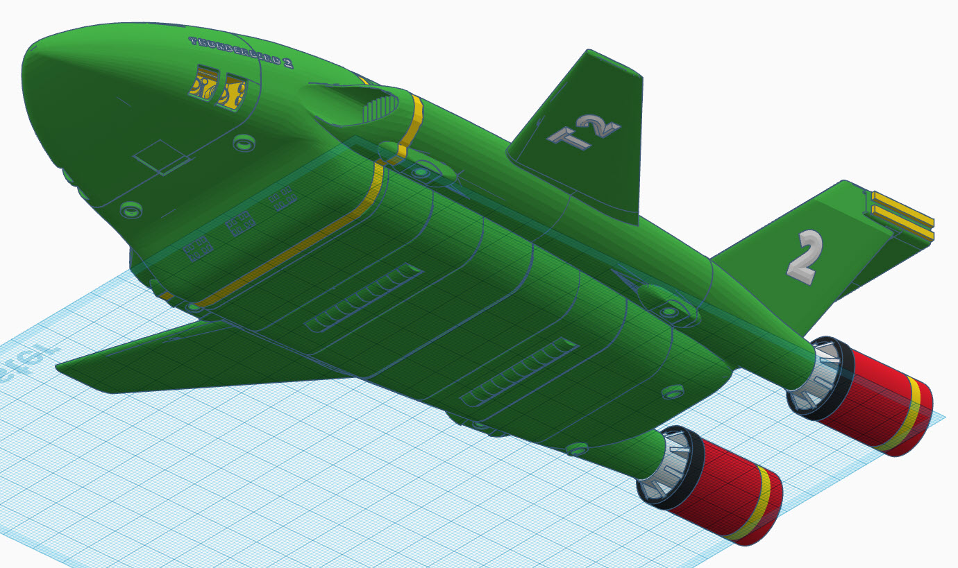
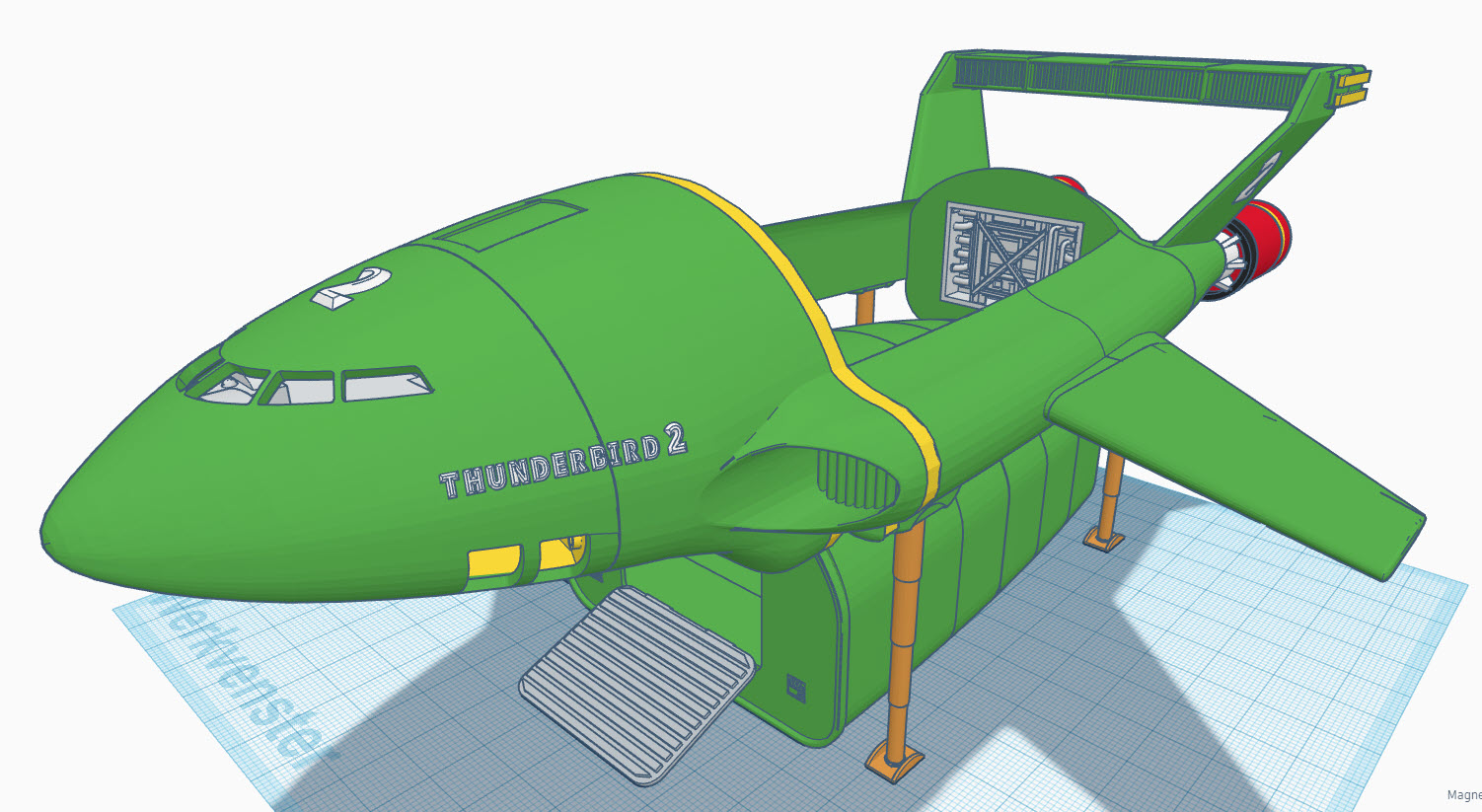
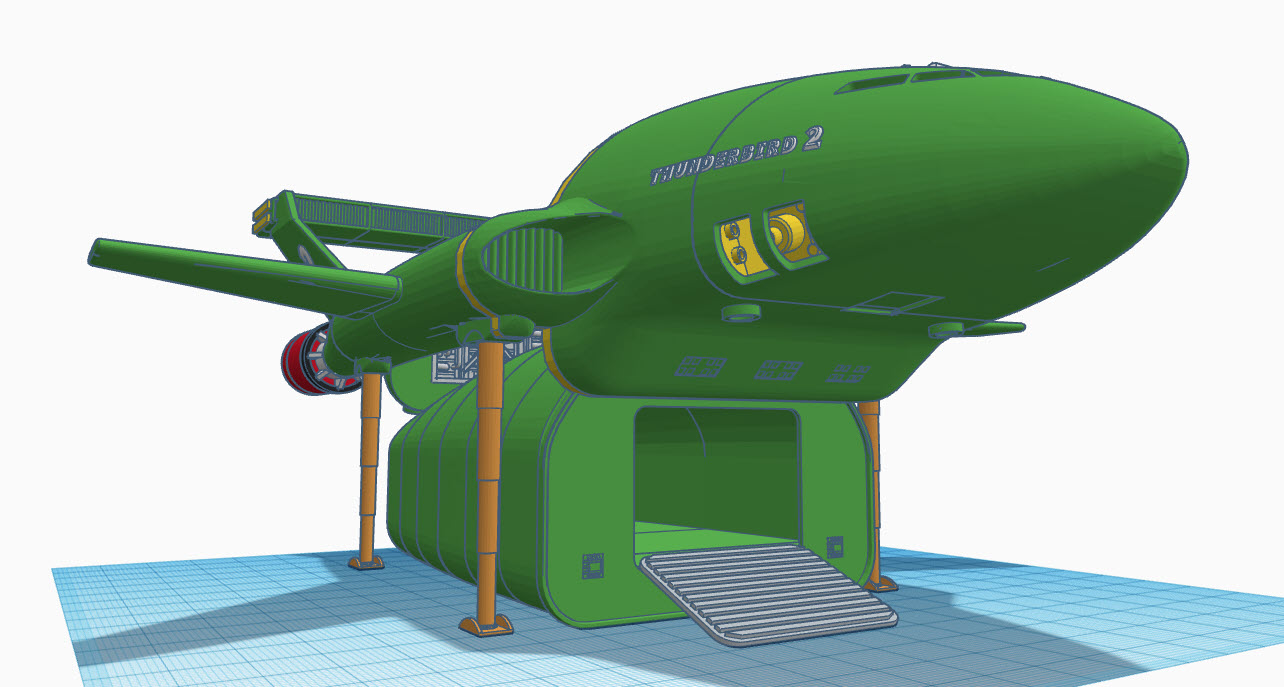
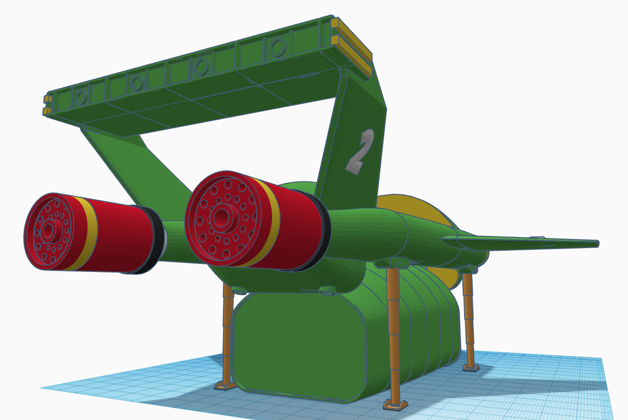
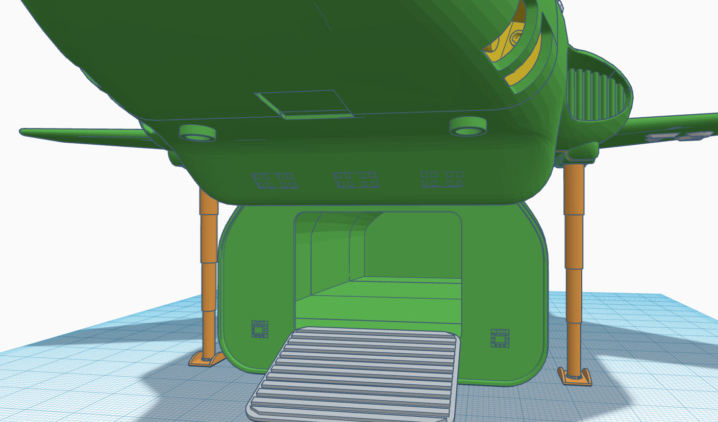
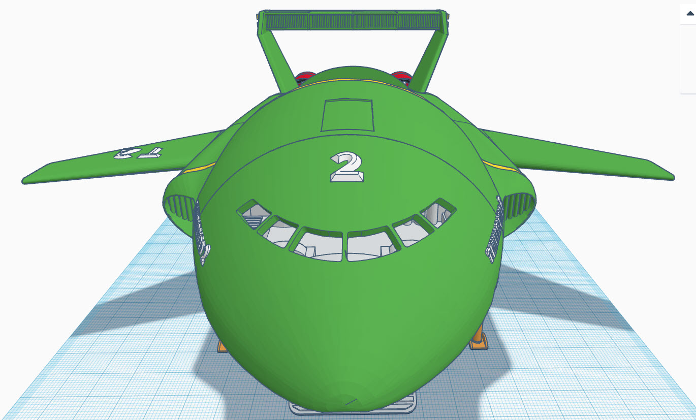
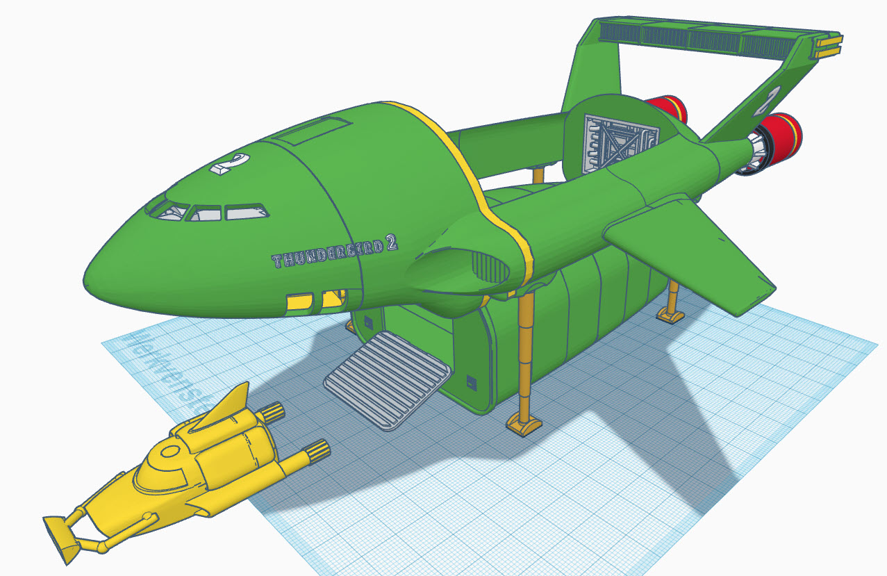
Thunderbird 2
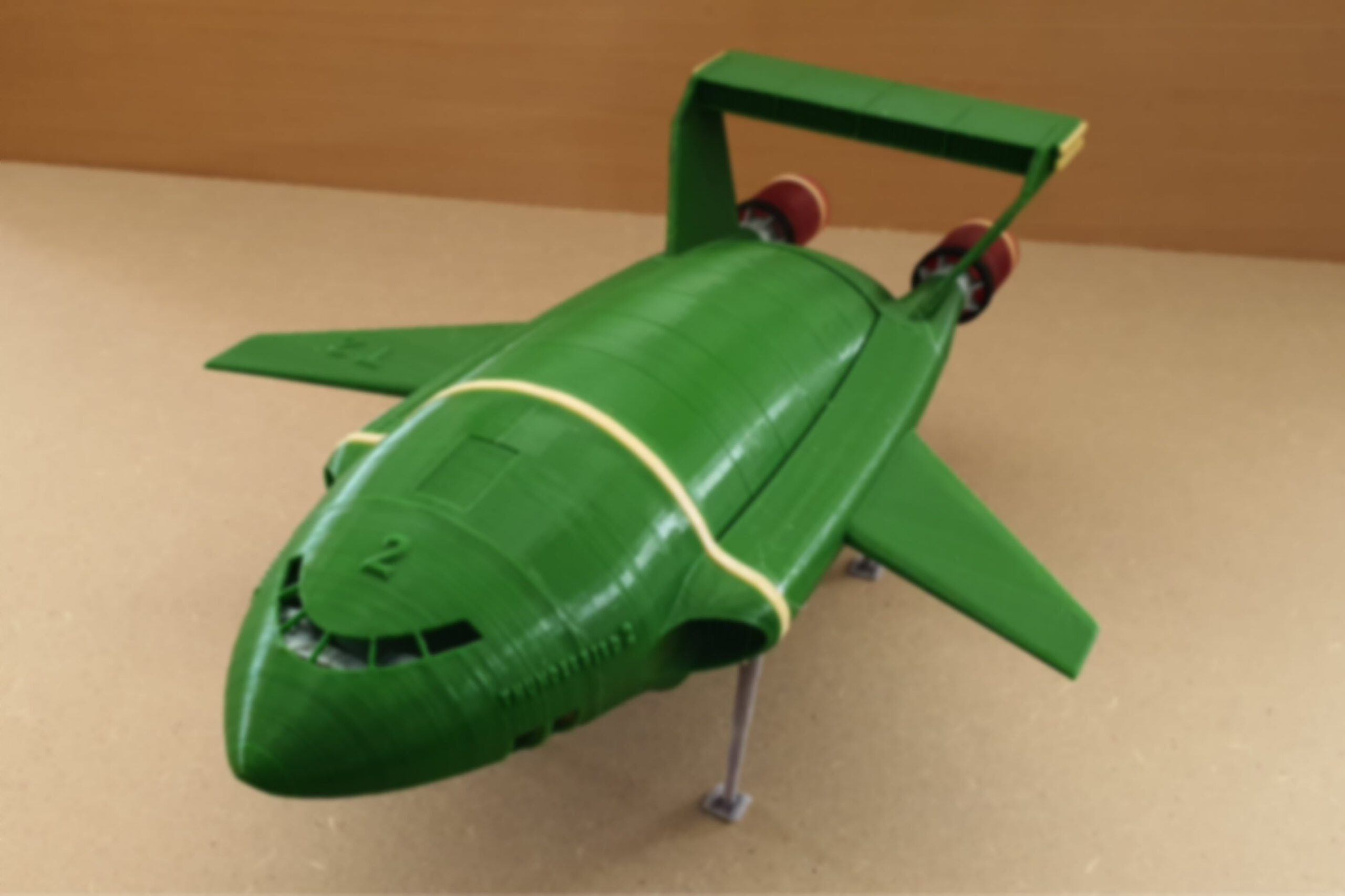
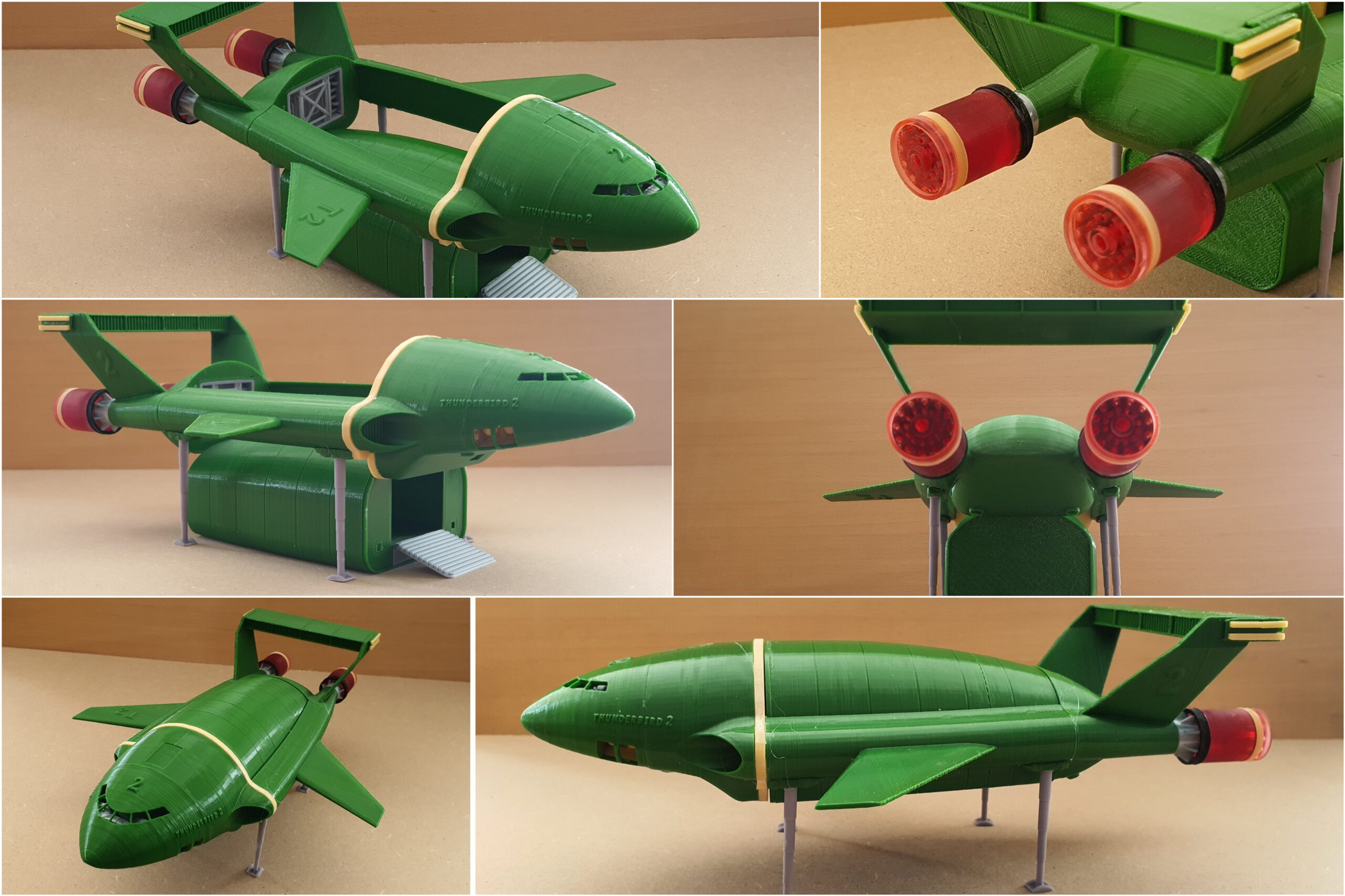
Of all the Thunderbirds, Thunderbird 2 is probably the one that presented the most interesting design challenges. Its huge flowing fuselage, the landing gear, removable pod and small external details make it much more than just a green shell with wings.
Thunderbird 2
Thunderbird 2
Thunderbird 2
Thunderbird 2
Thunderbird 2
Thunderbird 2
Thunderbird 2
Thunderbird 2
Thunderbird 2
Thunderbird 2
Thunderbird 2
Thunderbird 2
The landing gear cannot retract into the model. Because the mechanism is too delicate at this scale, but the legs can be removed if the model is mainly intended for display with the pod inserted. The tail and stabilizer sections are separate parts that slide into position, while small details such as lettering are designed so they can be printed separately in the appropriate colours.
Naturally, Thunderbird 2 wouldn’t be complete without a pod. I included one with the model — and even added a small one-piece Thunderbird 4 to live inside it.
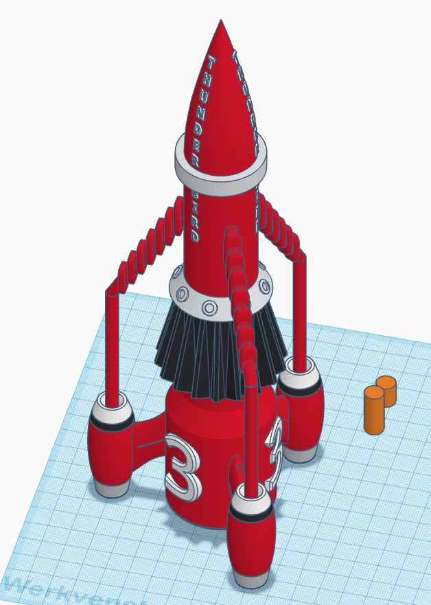
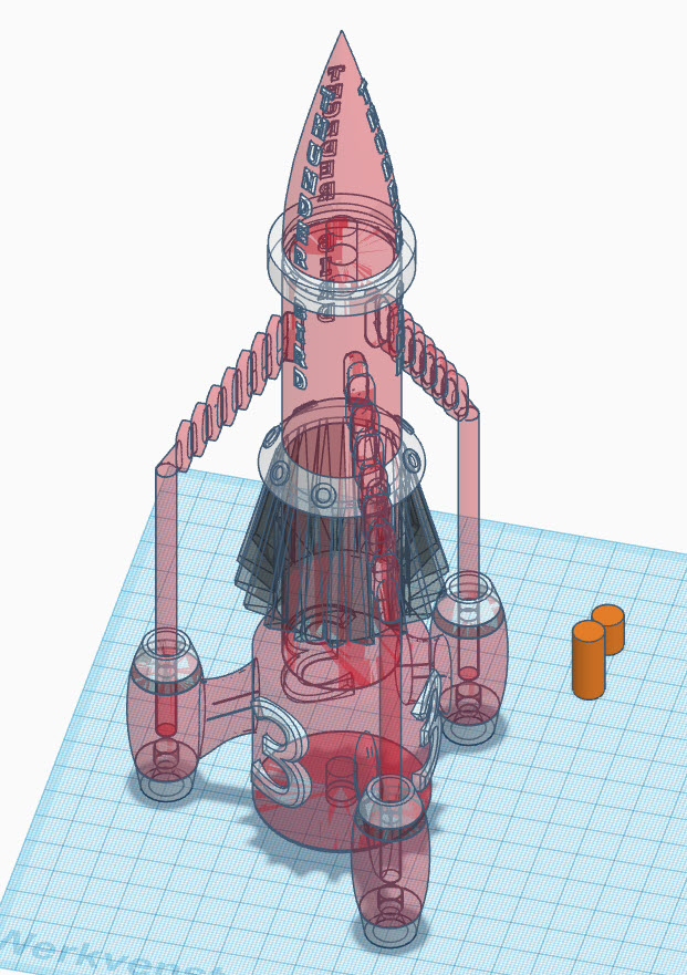
Thunderbird 3
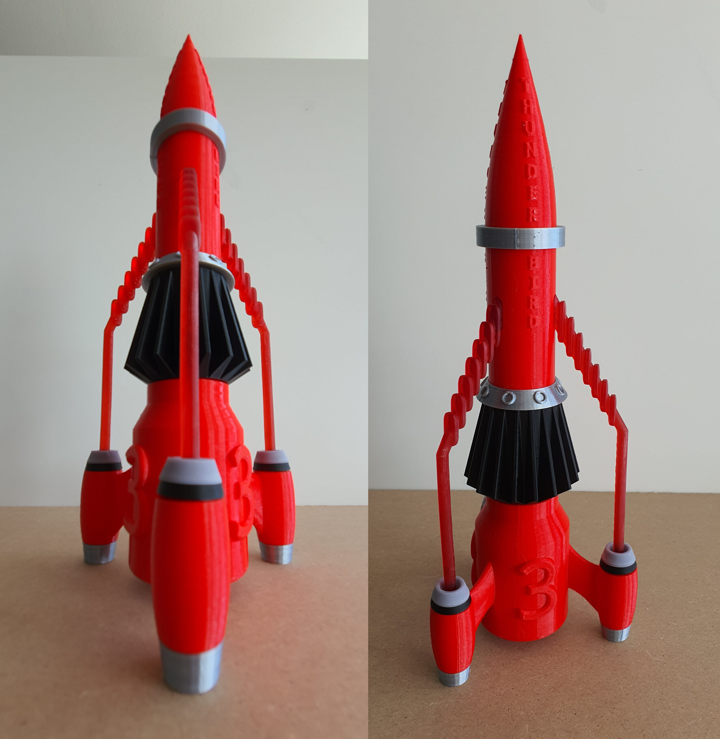
Thunderbird 3 is essentially a collection of long cylinders, fins and rocket engines — which sounds easy until you try to turn that distinctive shape into something that prints cleanly and assembles accurately.
Thunderbird 3
Thunderbird 3
Thunderbird 3
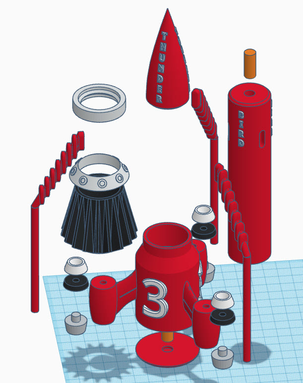
I split the model into colour-separated sections so that very little painting is required. Alignment dowels help keep the tall structure straight during assembly, while the individual components use roughly 0.2 mm clearance where they fit together.
Almost everything can be printed without supports; the jet arms are the main exception. As with the other models, I used SLA resin for the smaller detailed components and FDM for the larger structural parts.
The result is a model that looks suitably ready to leave Tracy Island vertically and in a great hurry.
STL Files TB3
I used an SLA printer for small detailed parts, and a FDM printer for the rest.
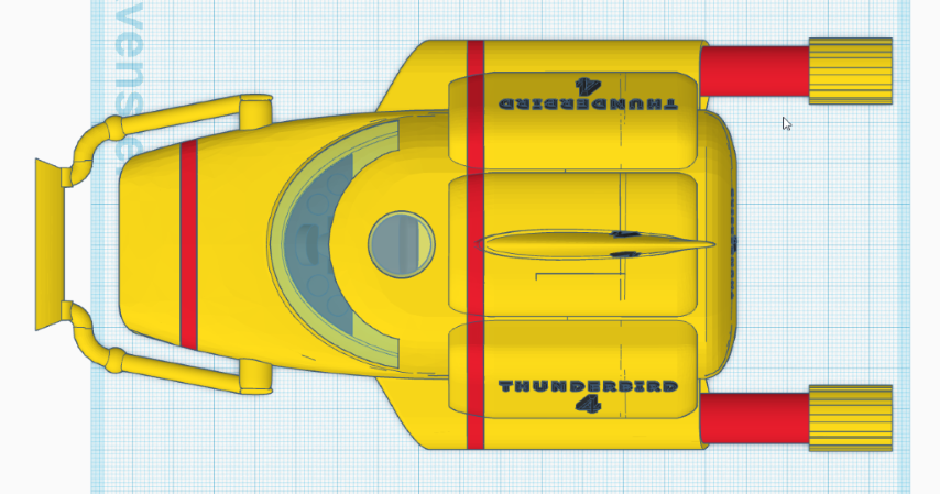
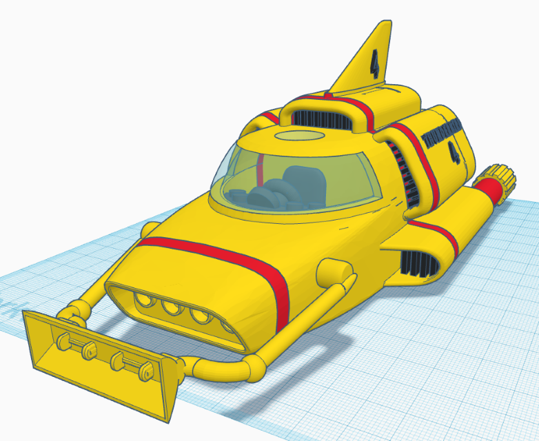
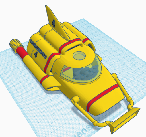
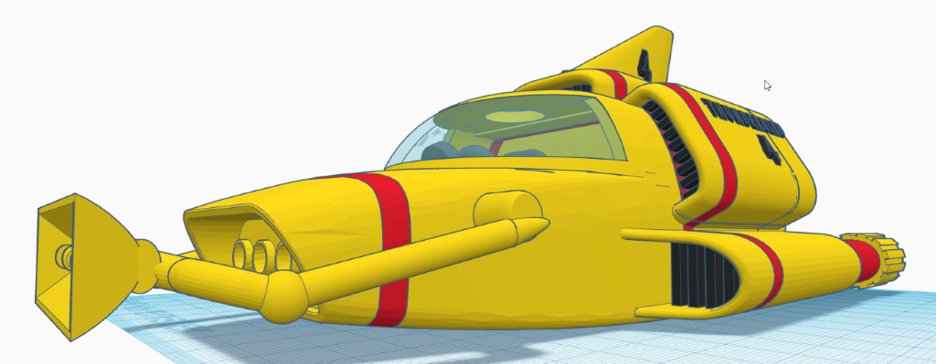
Thunderbird 4
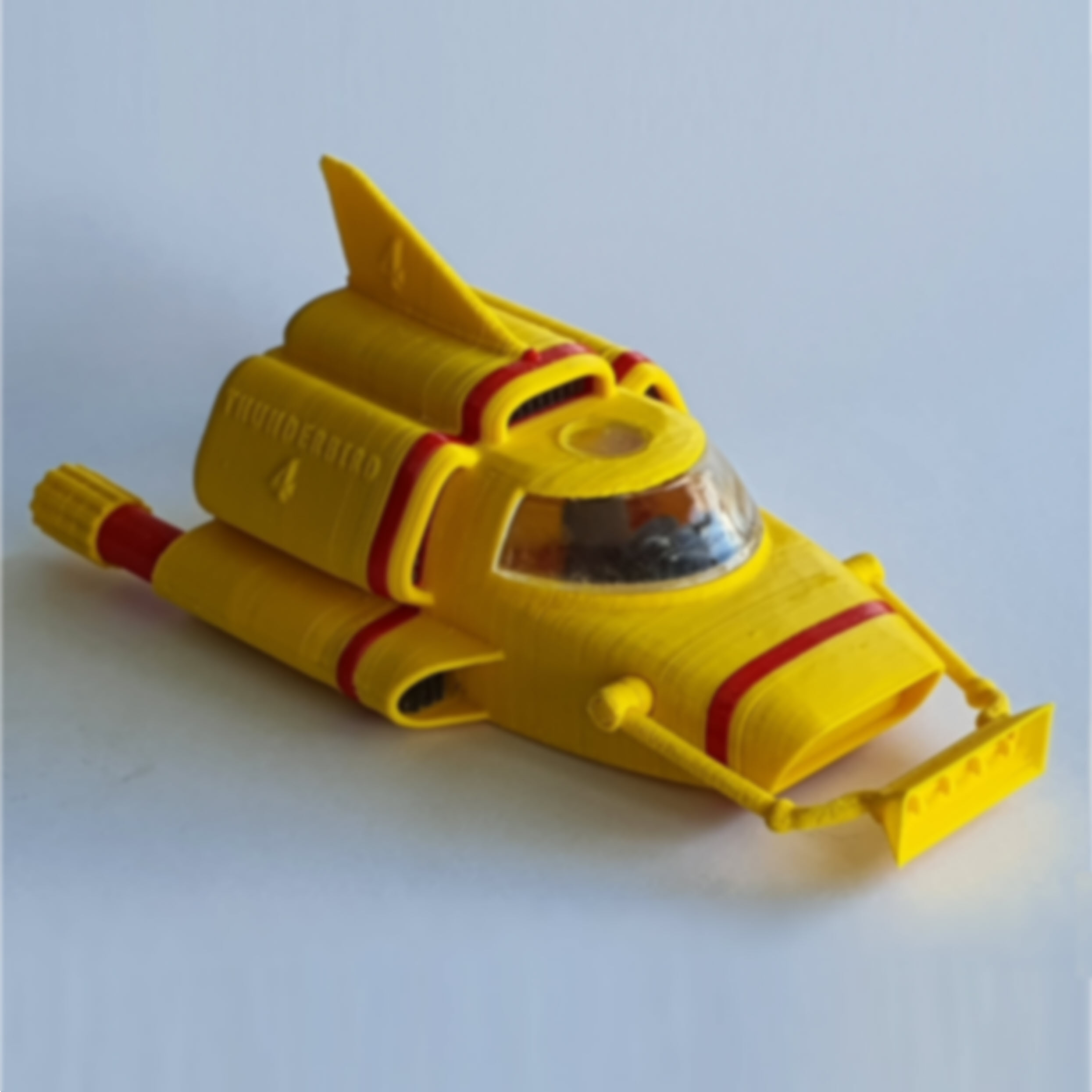
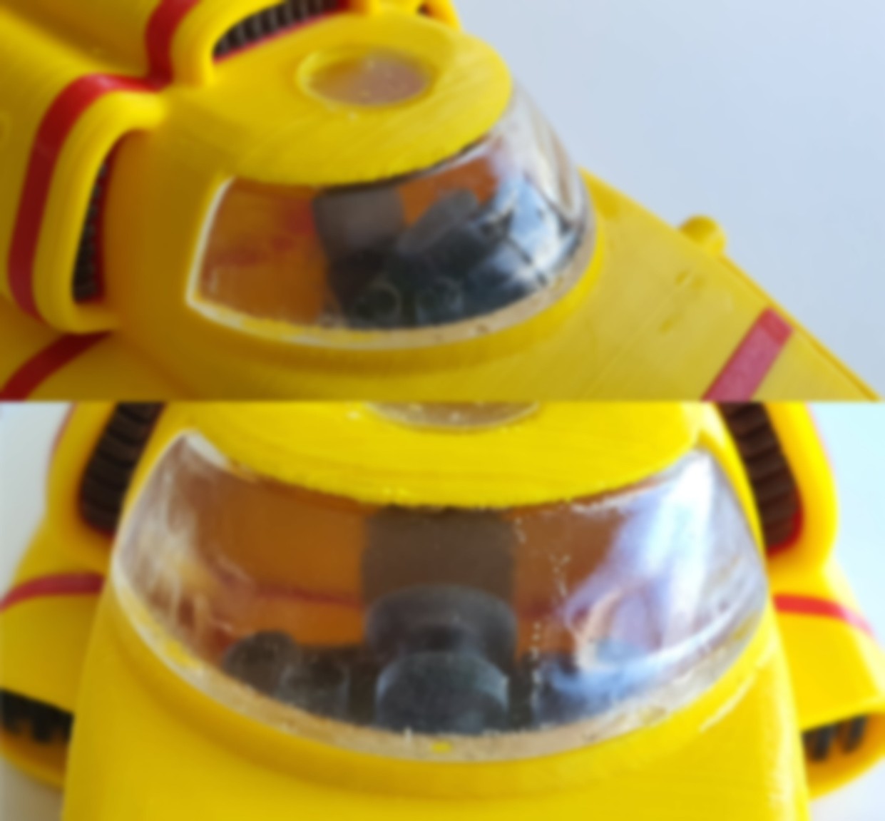
Smallest of the original Thunderbird machines, but for this model I deliberately gave Thunderbird 4 a larger scale of its own. That allowed me to preserve far more of the characteristic shapes and details of the little yellow submersible than would have been possible if it had been scaled to fit inside Thunderbird 2.
Thunderbird 4
Thunderbird 4
Thunderbird 4
Thunderbird 4
Thunderbird 4
Thunderbird 4
Thunderbird 4
Thunderbird 4
As with the other models, it is divided into separate colour parts wherever practical, minimizing the need for painting. Alignment dowels help position the components accurately during assembly, while the combination of FDM and resin printing makes it possible to retain the finer details without unnecessarily complicating the larger parts.
Thunderbird 2 does include its own miniature Thunderbird 4, but that is a separate, simplified one-piece model designed specifically to fit inside the pod. The model presented here is the full, larger and much more detailed version.
Small rescue craft, considerably less small 3D print.
Printing & Assembly
The models were designed with 3D printing in mind. Almost all parts can be printed without supports when oriented correctly. In some cases this means printing a part upright rather than in what might seem the most obvious position. A few parts inevitably require supports because of their geometry.
Tall or narrow parts printed upright can be more vulnerable to being knocked loose by the nozzle. If that becomes a problem, there are several ways to improve reliability:
Use a small amount of adhesive on the print bed to improve adhesion.
Enable Z-hop on retraction, so the nozzle lifts slightly while travelling over the print.
Add a raft to give tall or narrow parts a more stable base.
Parts that slide into or over each other were designed with approximately 0.2 mm clearance. This should provide a good fit on a properly calibrated printer, although minor sanding or adjustment may occasionally be required.
I printed the small, highly detailed parts on an SLA resin printer, as many FDM printers may struggle to reproduce the finer details cleanly. The larger structural parts were printed using FDM.
The STL filenames include both the intended colour and the number of copies required, making it easier to prepare the complete set of parts before assembly.
As always with 3D printing, printer calibration, material choice and slicer settings can make a difference — so consider the tolerances and print orientations a starting point rather than a law of nature.
Building a Motorized Dobsonian Telescope Mount in My Living Room
I’ve built and modified things for as long as I can remember.
Most of my earlier projects revolved around home improvement rather than hobby projects. I always repaired our household appliances myself, something I learned from my father, who was both highly technical and incredibly handy. In my younger years I also maintained my own motorcycle. Every winter it came apart completely and went back together piece by piece.
My educational background reflects that fascination with technology. I started with vocational school (LTS) and technical college (MTS), both focused on electrical engineering, with additional training in machining and mechanical design. Later I graduated in electronics engineering (HTS), and many years afterward I added an MBA. Technology and making things have always been part of who I am.
Long before the existence of my current 9 m² workshop – the 9m² Creatory – all of my projects were built in whatever space I had available. Which, in this case, was our living room.
And that is where this story begins.
The old Bynolyt
For many years I owned a Bynolyt Bynostar 4595 Newtonian telescope. A modest instrument by modern standards, but one that had accompanied me for nearly thirty years.
Specifications:
Aperture: 114 mm
Focal length: 900 mm
Focal ratio: f/7.9
2× Barlow lens
H-20 mm and H-6 mm eyepieces
At some point I became fascinated by astrophotography and wanted to automate the tracking of celestial objects. A traditional Dobsonian mount is manually operated, but I wondered whether I could build a fully motorized version myself.
Naturally, the answer was “why not?”
Starting with Wood
Like many Dobsonian builders, I started with wood.
The first design was created entirely in 2D using an ancient CorelDRAW X7 version. Fusion 360 and things like parametric design would only enter my life a few years later. The mount itself was built from waterproof MDF, which was later treated even further against moisture.
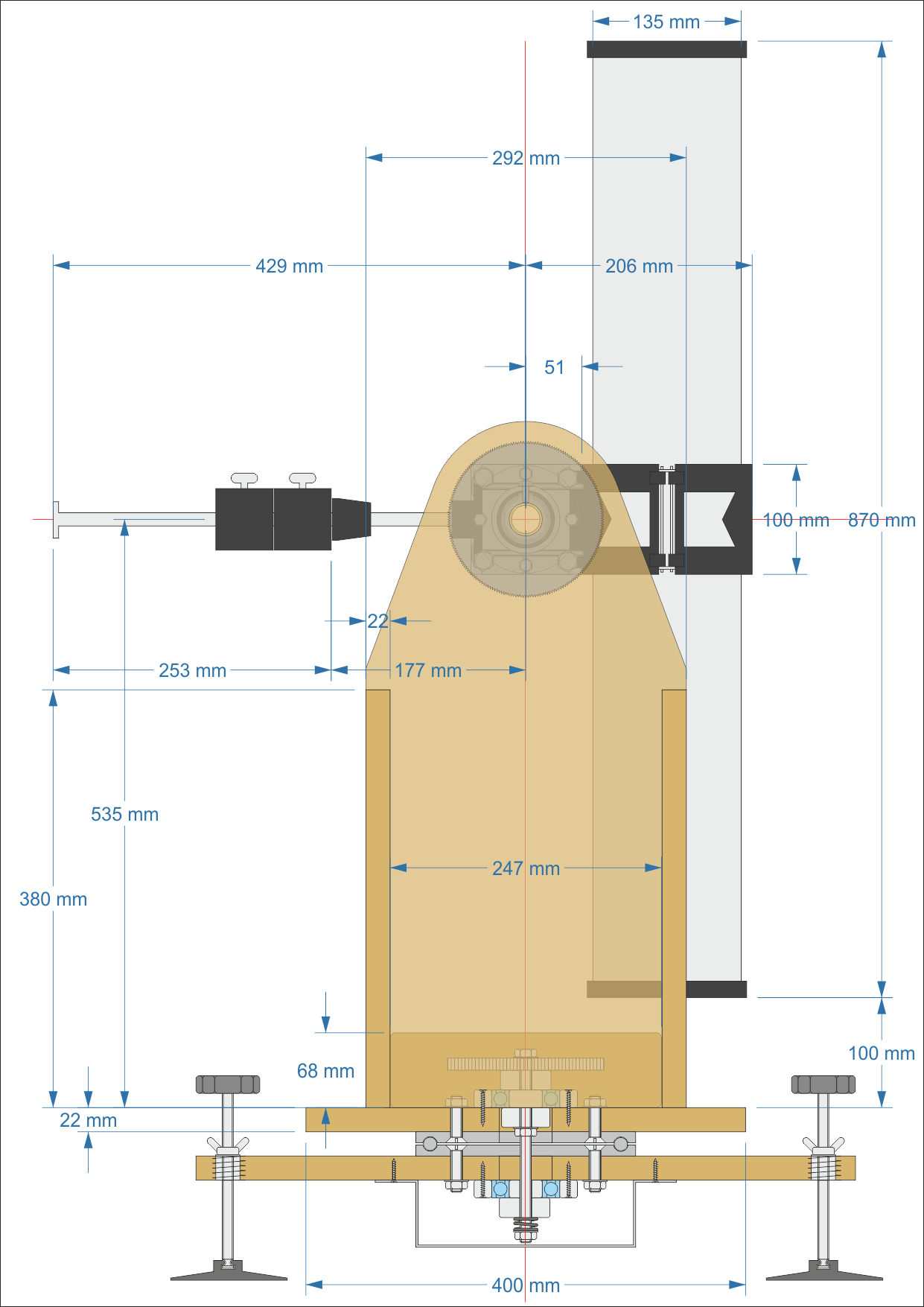
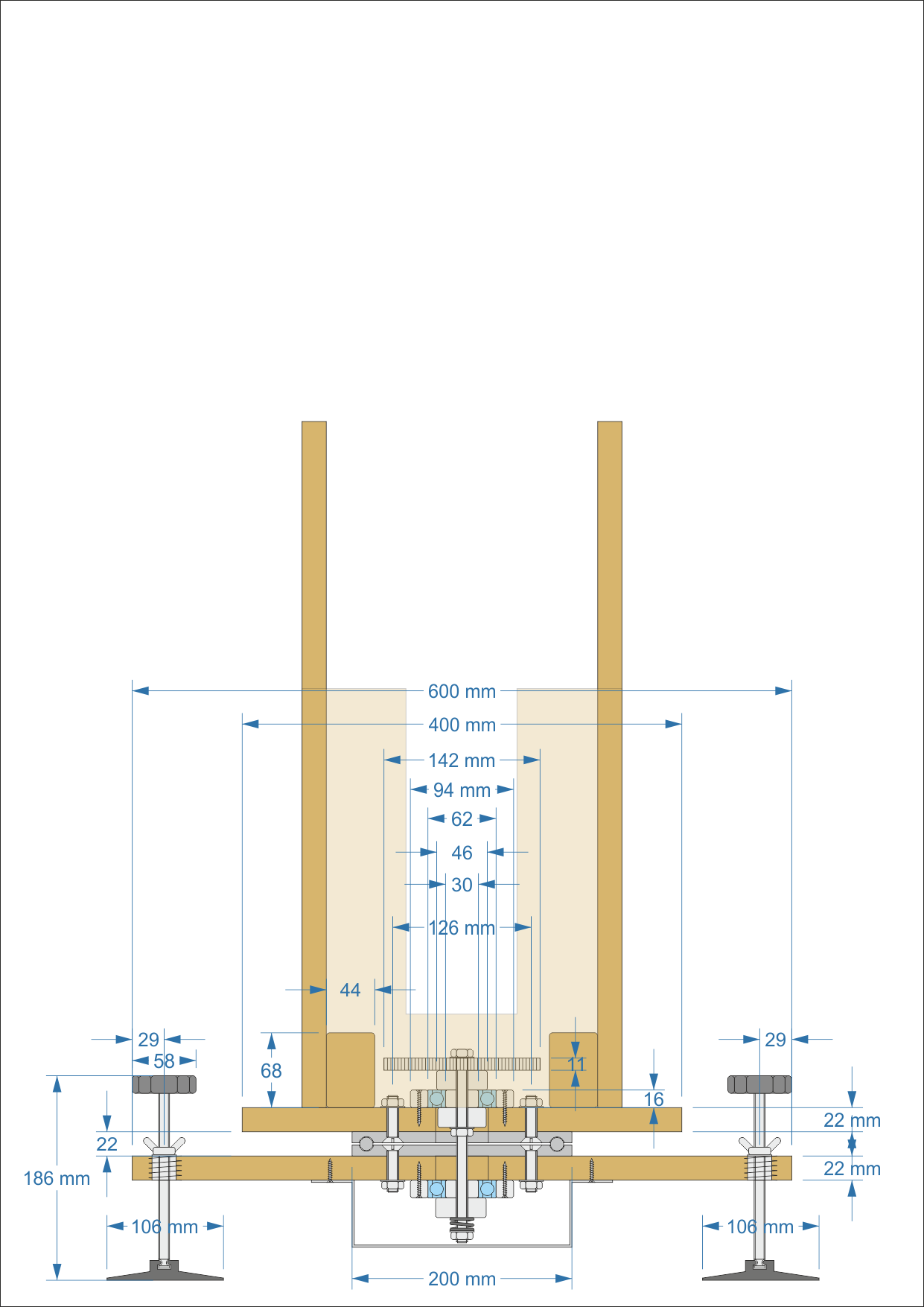
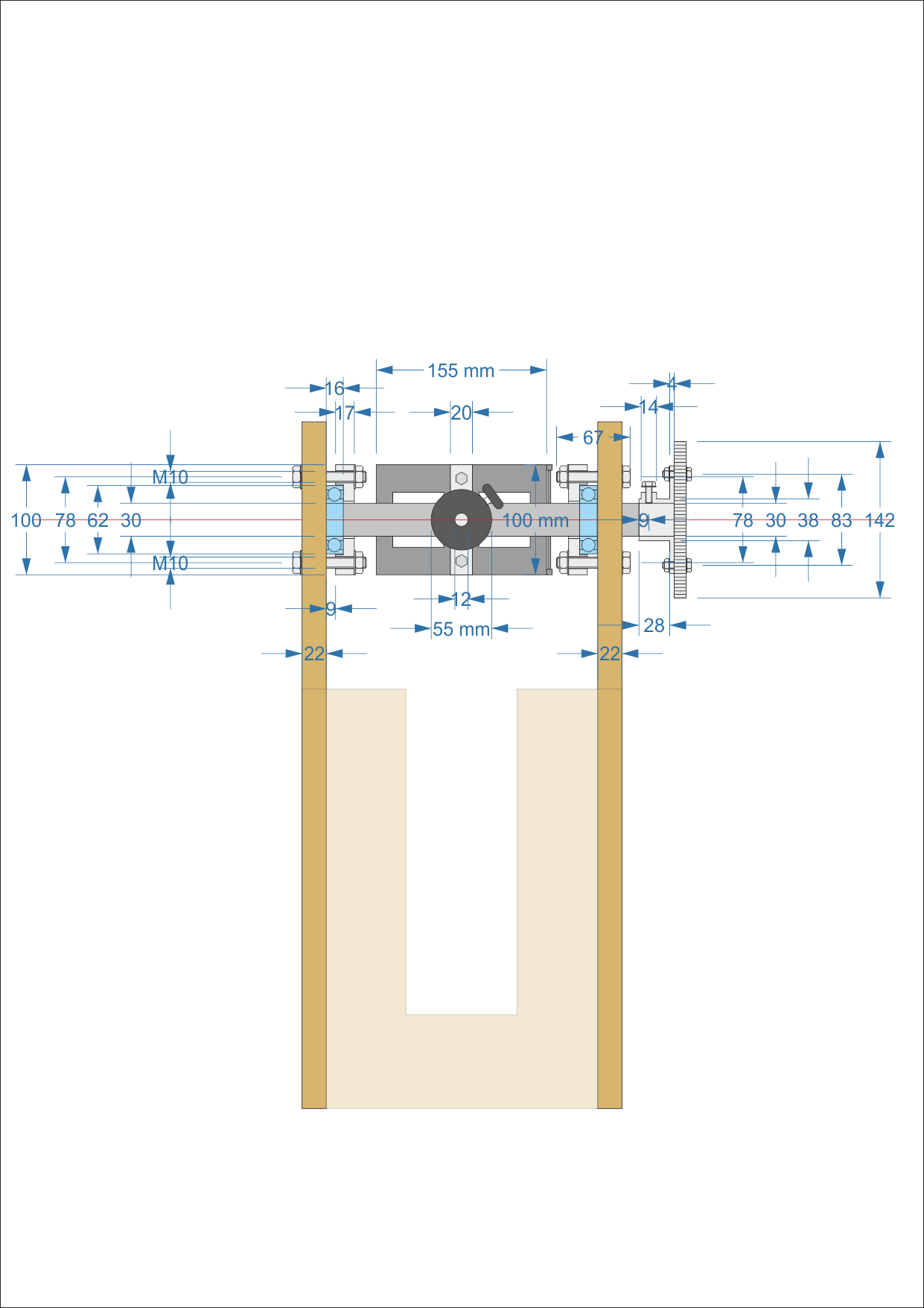
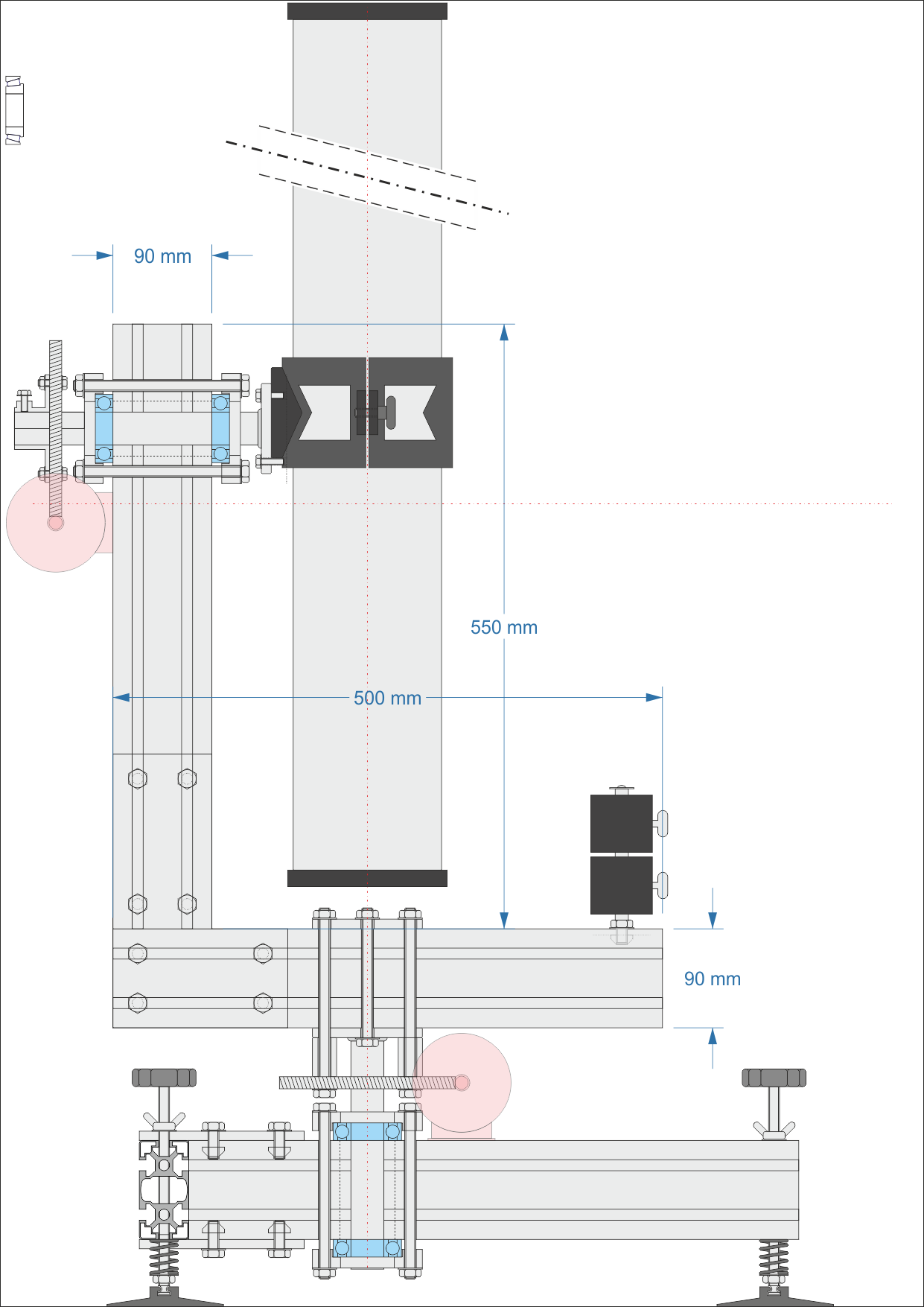
Front View
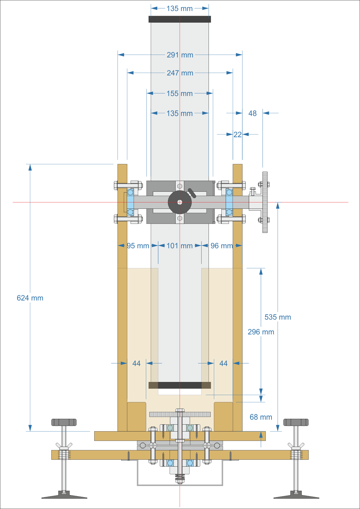
Side View
Ground Board Detail
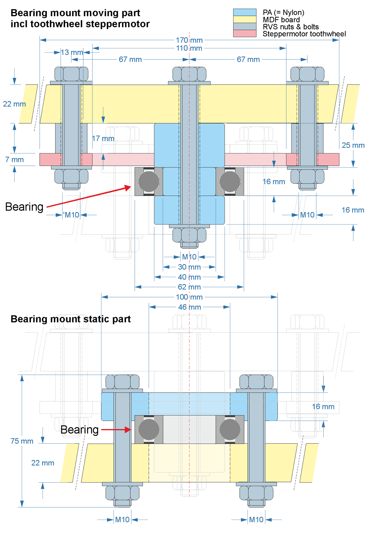
Altitude Bearing Detail
The design was fairly conventional, using a rotating ground board for azimuth movement and a horizontal altitude axis supported by side bearings.
The First Working Mount
Eventually the design became reality.
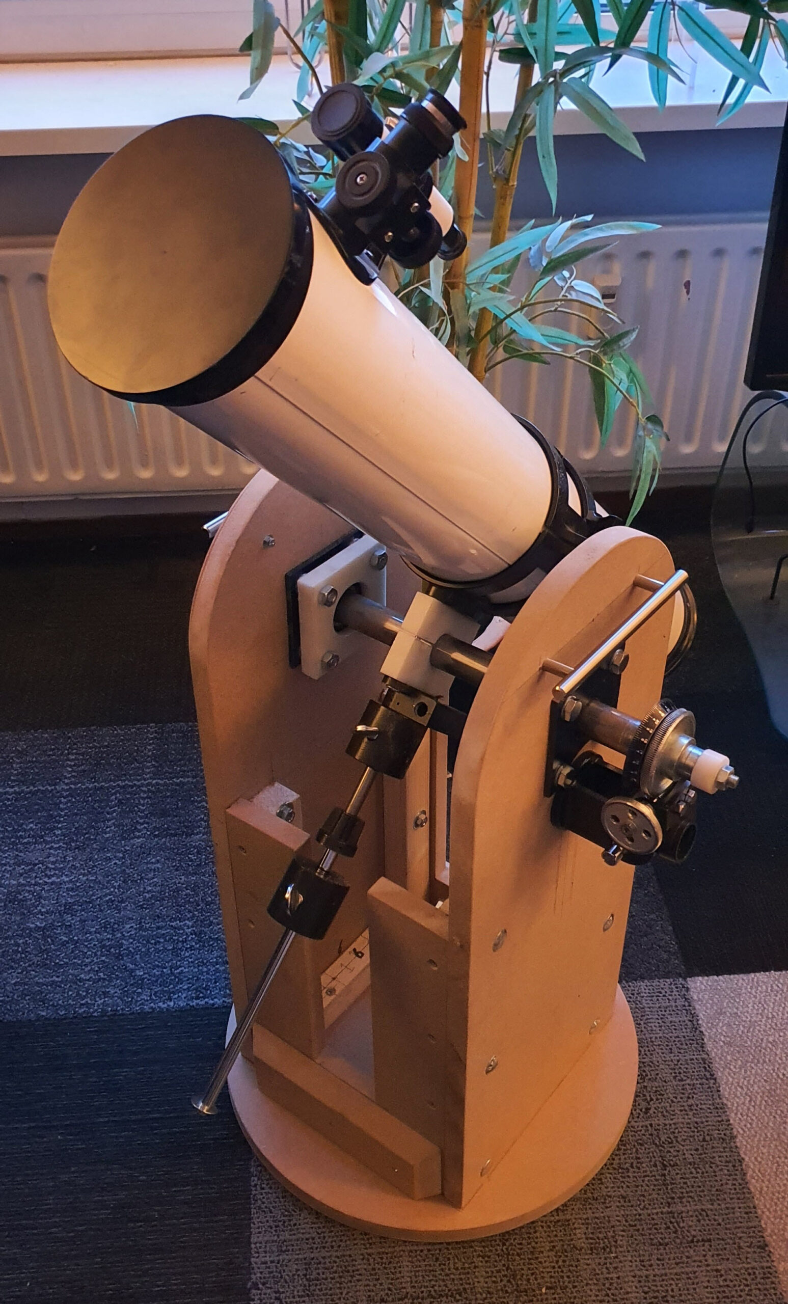
Wooden Dobsonian Mount
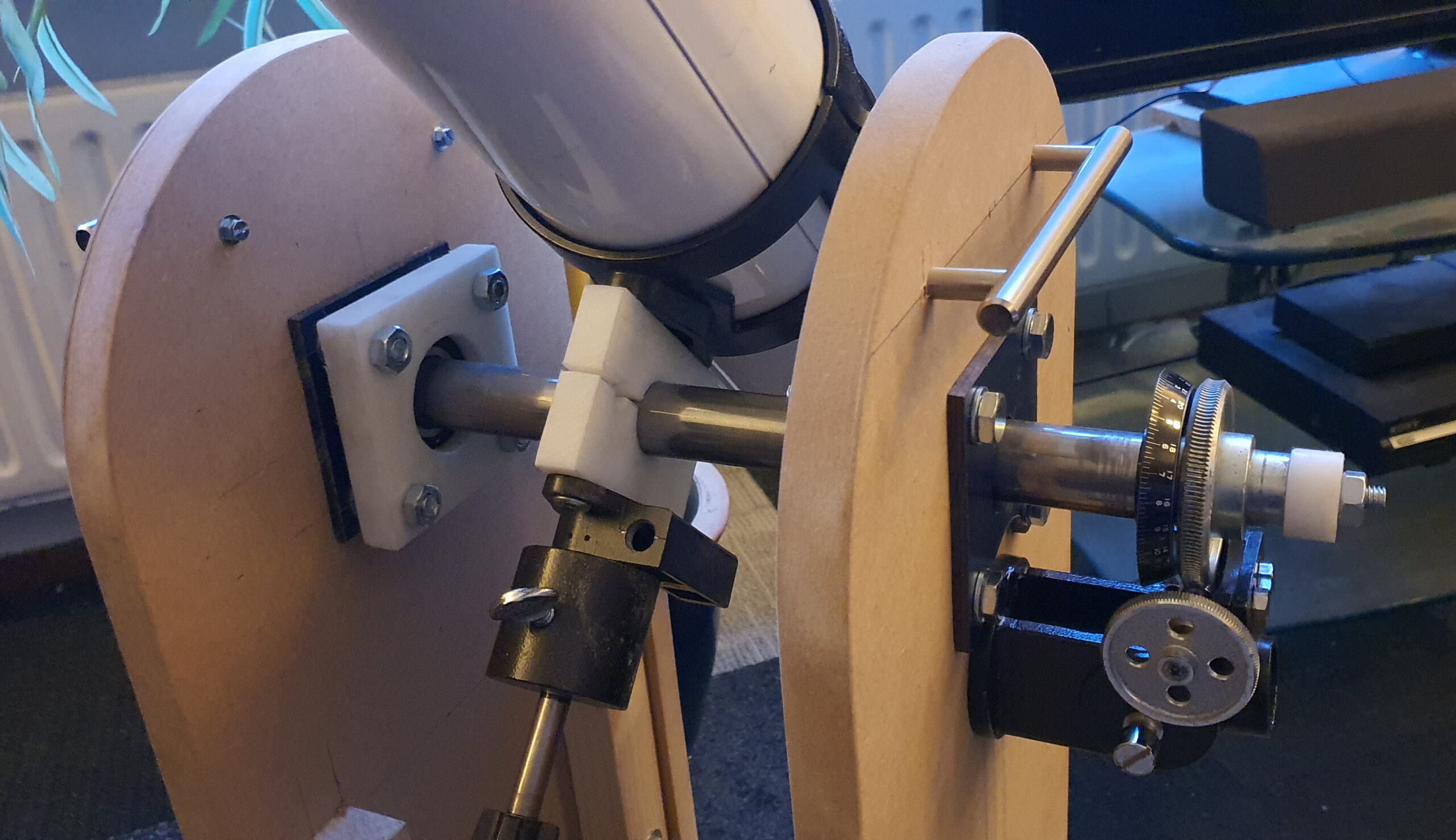
Wooden Dobsonian Mount – Detail
The telescope itself was suspended between two side panels, and the altitude axis was driven through a worm gear arrangement. It worked surprisingly well and, looking back, the wooden construction had one major advantage:
It was light. An advantage I would only fully appreciate later.
Inspiration from the Internet
While searching for ideas, I came across an inspiring project by another enthusiast who had built a Raspberry Pi powered tracking mount.
That project convinced me that I could push my own design much further. And… Inspired by that work, I decided to redesign the entire mount from scratch.
This time in aluminium. After all, aluminium had to be better… right?
Enter Aluminium
The new mount became far more ambitious.
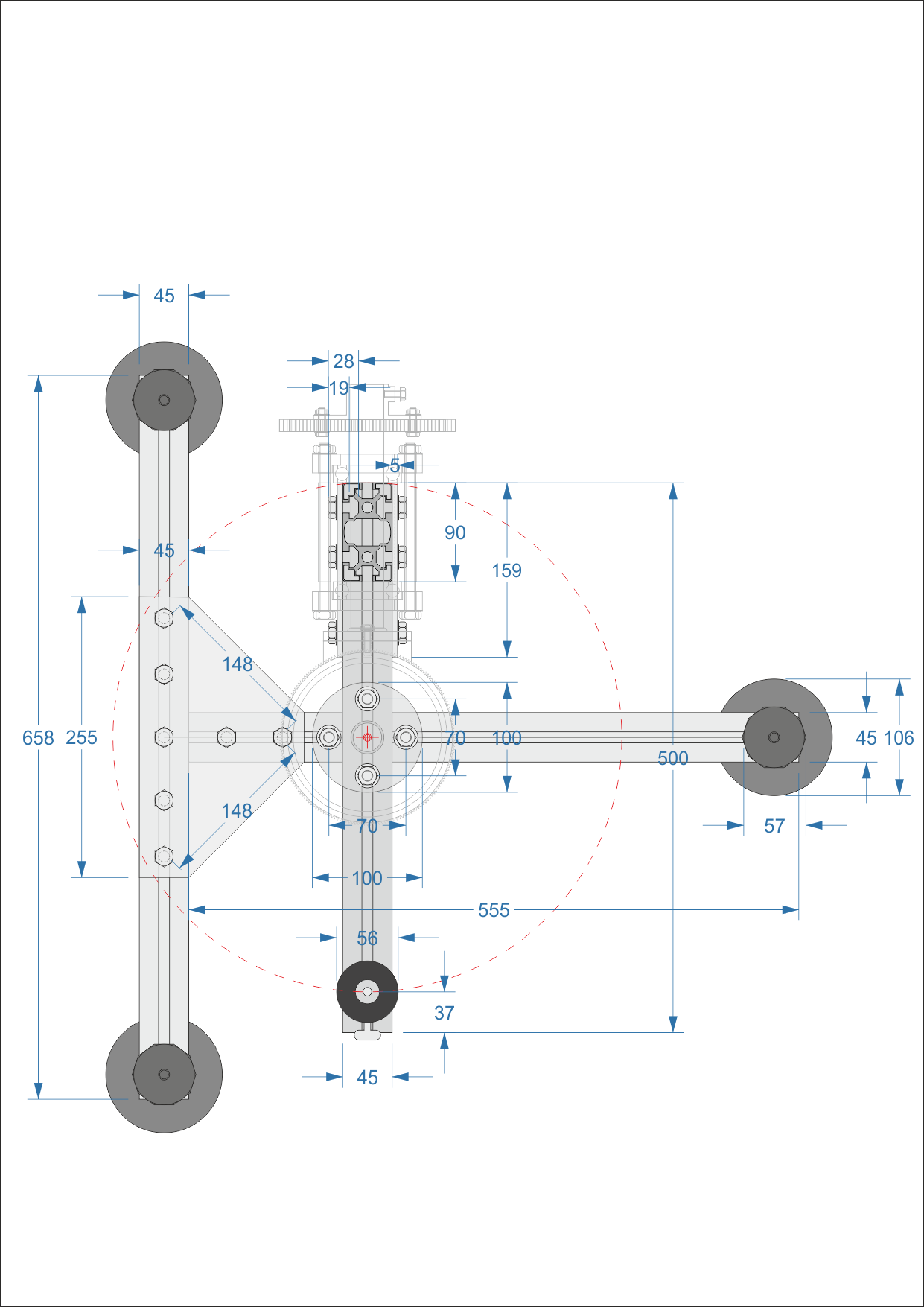
Instead of wood, the structure was built around aluminium profiles. Electronics would live inside laser-cut acrylic enclosures. Bearings, gears, chain drives and stepper motors would provide motion on both axes.
Front View
Top View
Pivot Detail
By then I was already becoming increasingly obsessed with mechanics and precision. Looking back at those drawings, I still smile. They were all made in 2D. Fusion 360 and fully parametric 3D design were still in the future.
When Your Living Room Becomes a Workshop
At that time, there was no 9m² Creatory.
There was only our living room.
My living room as a workspace
Soldering irons, electronics, tools, wires, aluminium profiles, stepper motors and telescope parts were scattered everywhere. My wife deserves a medal for putting up with it.
But little by little, the system came together.
The Final Machine
Eventually the project evolved into something far beyond the original wooden mount.
Photo 11 – The finished aluminium mount
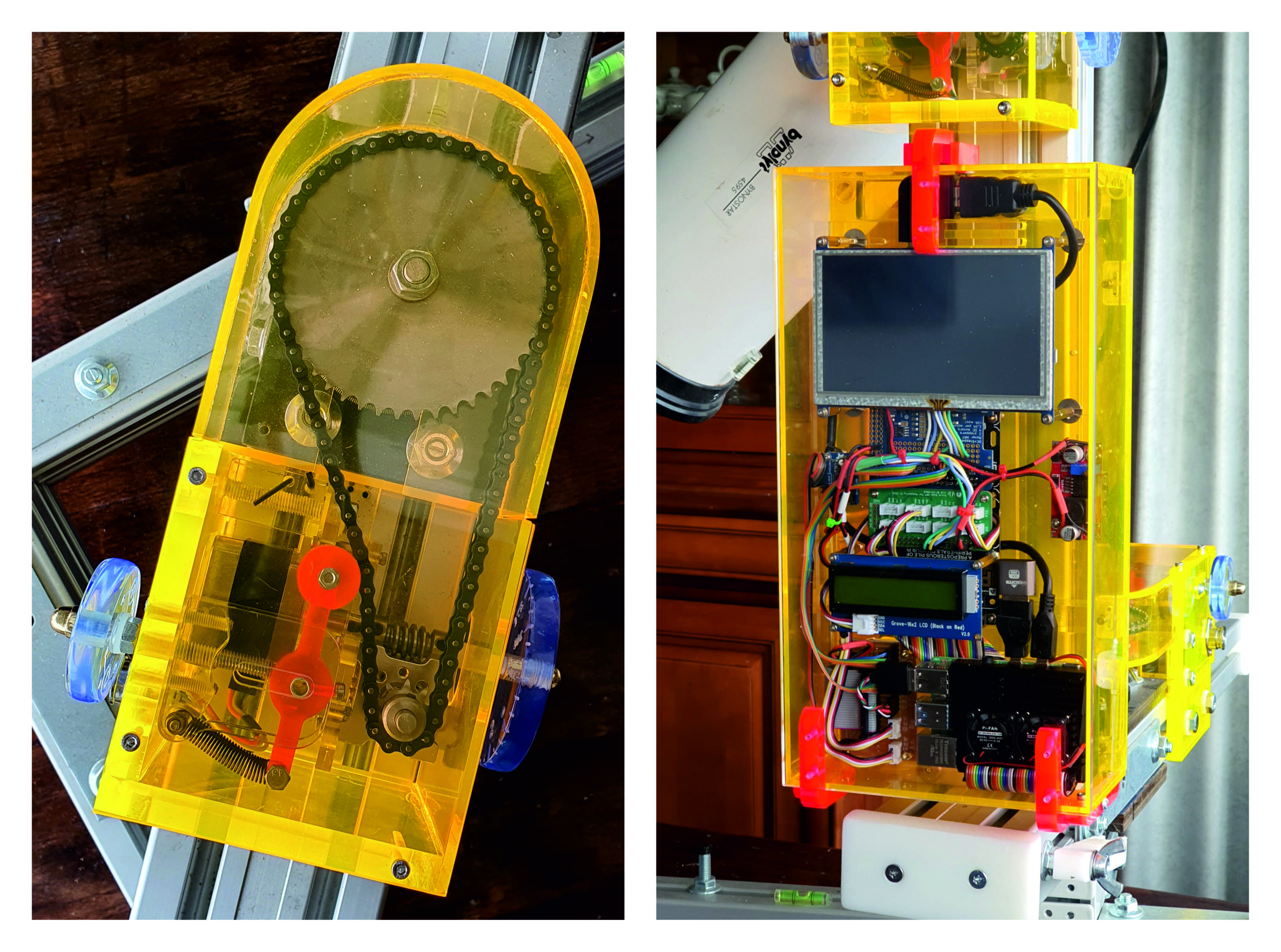
The frame consisted mainly of aluminium profiles, while most enclosures and mechanical parts were fabricated from colored acrylic.
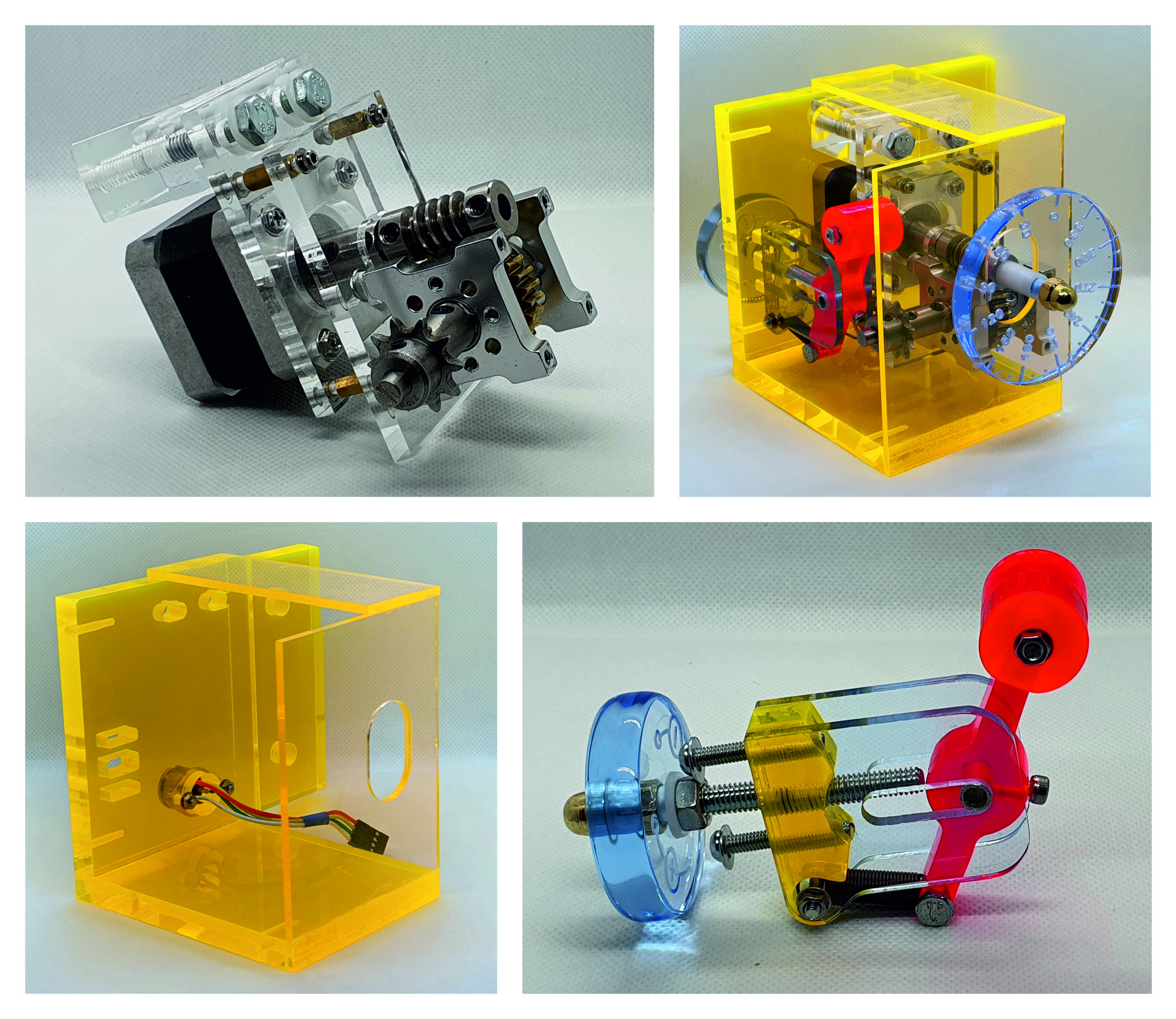
The yellow transparent covers became something of a signature look. Through them you could see chains, gears, springs and adjustment mechanisms moving while the mount tracked the sky.
ALU Dodsonian Mount – Detail 1
ALU Dodsonian Mount – Detail 2
Inside the acrylic housing lived the electronics, display, motor drivers and control hardware. I always liked making the mechanics visible instead of hiding them away.
Some Valuable Lesson
Unfortunately, the aluminium version introduced a problem I had underestimated.
1. Weight.
The moving section became significantly heavier than the original wooden design. Every step made by the stepper motors induced a tiny amount of oscillation. After each movement, the structure would “waggle” ever so slightly.
For visual observing that wasn’t much of a problem.For astrophotography, however, those vibrations translated directly into softer less sharp images.I spent quit some time trying to eliminate that behaviour but never managed to get rid of it completely.
Ironically, the simpler wooden version had actually been the better engineering solution.
Sometimes lighter really is better.
2. The Chain
Looking back, I eventually traced most of the oscillation problem to the chain drive itself. Tightening the chain reduced the wobble, but at the same time increased friction and load on the stepper motors, which then struggled to deliver smooth motion. Leaving the chain looser reduced the load, but introduced just enough compliance to allow the whole assembly to oscillate after each step.
In hindsight, a properly engineered worm gear and worm wheel arrangement would probably have been the better solution, but by then I had already invested a considerable amount of time into the existing design and never got around to redesigning it. The inexpensive bearings I had used also exhibited a tiny amount of play, which proved to be a poor combination with a heavily tensioned chain drive. Eventually, I settled on what engineers everywhere sometimes have to accept: good enough. I knew I wasn’t extracting the maximum performance from the system, but it performed well enough to continue enjoying the project rather than endlessly chasing perfection.
The Telescope Had Aged Too
By that time, my old Bynolyt had nearly thirty years of service behind it.
It had accumulated a bit of “field damage”, and I strongly suspected that the primary mirror needed realignment. Unfortunately, I never got around to restoring it.
Two years later I sold the complete setup to another hobbyist who was particularly impressed by the aluminium mount. He planned to replace the Roller bearings and the chain mechanism (by a worm gear) and use it with a heavier telescope, which suited the construction better.
The new owner also had a clever workaround in mind. Rather than fighting the tiny oscillations mechanically, he wanted to use a precision accelerometer and delay the camera exposure until the mount had completely settled after each movement. I always liked the simplicity of that idea, but I never learned whether he succeeded in getting it to work.
A nice surprise though…
One unexpected highlight came much later. One fun detail worth mentioning is that the yellow acrylic used throughout the project wasn’t chosen purely for aesthetics. I had deliberately selected a fluorescent variety that reacts to ultraviolet light and appears to glow from within. It’s the same type of material often used in nightclubs to create those dramatic blacklight effects. Under UV illumination, the mount looked like something straight out of a science fiction movie—which, admittedly, I considered a nice bonus.
About a year later, I entered the design in a competition dedicated to projects made from acrylic. To my surprise, I won second prize. One of the comments from the jury was that they particularly appreciated the futuristic appearance of the design, with its visible mechanics and translucent glowing panels. Not bad for something that had started life on the dining table in our living room.
Looking Ahead
Several years later I entered a new chapter in my Astronomy hobby and purchased a completely electronically controlled telescope: a Seestar S50 Pro.
Being incapable of leaving things alone, I eventually built an equatorial mount for it as well. Tracking celestial objects around a single axis instead of two significantly improves stability and image quality.